2022
Proceedings of the 18
th
International Conference on Soil Mechanics and Geotechnical Engineering, Paris 2013
as suggested by Terzaghi and Peck (1948), then the interpreted
drained friction angle would be between 47º and 52º with an
average of 50º. The inferred friction angle value is higher than
the measured friction angle from the direct shear test, but is
close the value that would be expected for the plane strain
friction angle. The conditions and geometry of the sand box
simulated a plane strain condition as well. Based on a number
of studies, Kulhawy and Mayne (1990) determined that the
plane strain friction angle for dense sand was 11% higher than
the triaxial value on average. Thus, the plane strain friction
angle for the sand used in the tests would be about 51°, which is
approximately the same value as that of the inferred friction
angle from the inclination of the failure wedge.
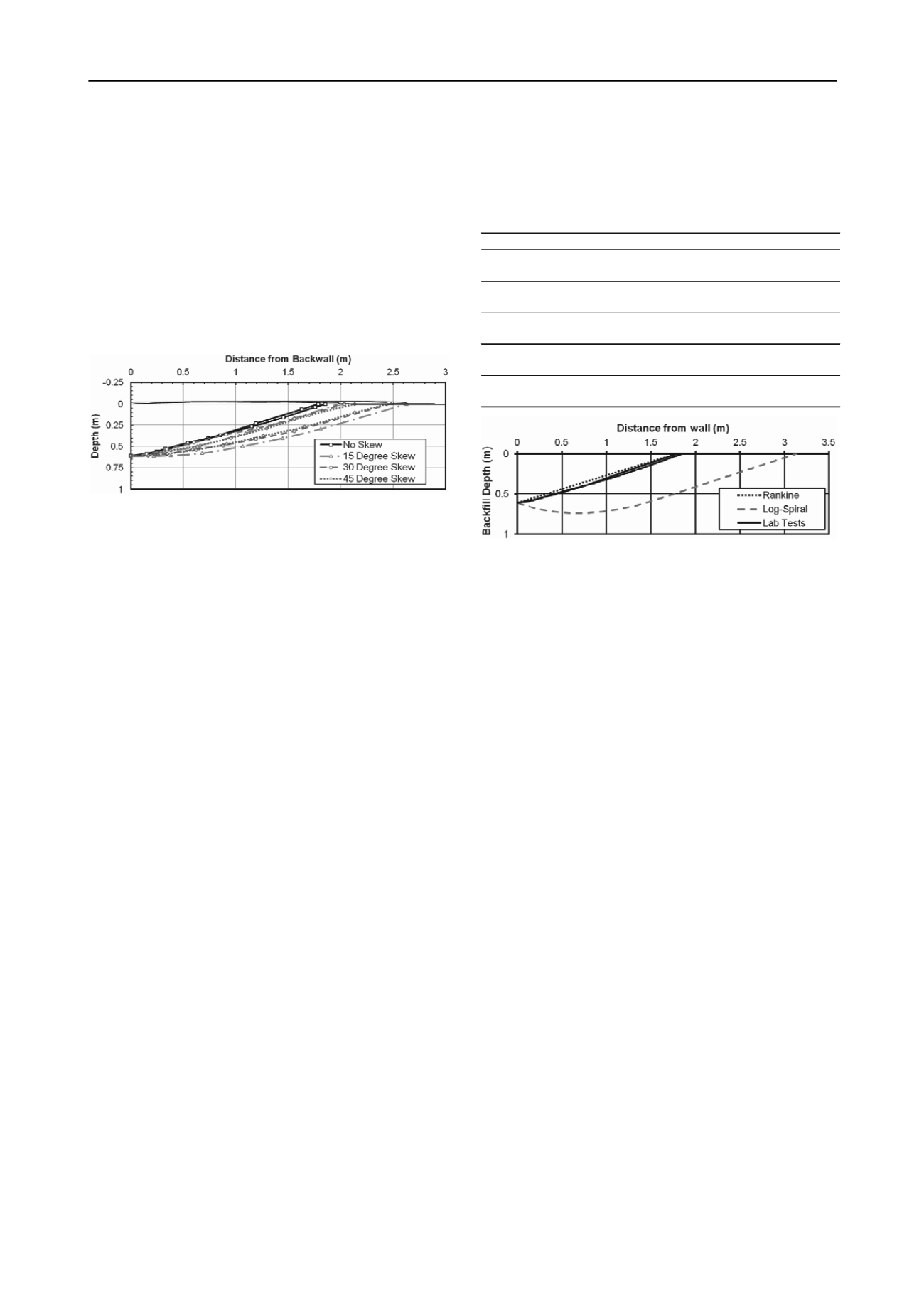
Figure 5. Measured failure surface depth versus distance from the
backwall for each test.
4 ANALYSIS OF RESULTS
Test results were analyzed using the Rankine (1857) and log-
spiral (Terzaghi, 1948) passive pressure theories. Table 1 shows
comparisons of the test results with computed passive force and
failure surface orientation for the no-skew case. The measured
and theoretical failure surface geometries for the no-skew case
relative to the top of the wall are shown in Fig. 6. For the
analysis, the soil friction angle was taken as 50°, consistent with
the plane strain value, with a cohesion of 4.5 kPa (90 psf), and
the wall friction angle was taken as 33° based on interface tests.
While the failure plane according to the log-spiral method
generally exceeded the length of the failure surface by 45 to
50%, this method was most effective in computing passive
force. In contrast, the Rankine method grossly underestimated
the measured force, but gave a reasonable approximation of the
failure surface geometry. Although the Coulomb theory is
widely used, it is limited to cases where δ/
ϕ
is less than about
0.5. For these tests, δ/
ϕ
is equal to 0.66. Thus, analyses using
the Coulomb method predict an unreasonably high value for the
passive force, and the failure surface extent is likewise
unreasonably over-predicted (see Table 1).
5 CONCLUSIONS
1. Large scale laboratory tests and numerical analyses indicate
that the peak passive force for a skewed abutment significantly
decreases as the skew angle increases. Based on available
results, this reduction can be accounted for by using a simple
reduction factor. This reduction may be dependent on abutment
geometry and other unknown factors and should thus be used
with caution until further research is performed.
2. For the dense sand typical of approach fills, the peak passive
force for all tests typically developed at longitudinal deflections
between 0.025H and 0.035H. However, the shape of the passive
force-deflection curve up to the peak value transitioned from a
typical hyperbolic shape for the no skew case to a bilinear shape
for the skewed walls.
3. At wall displacements beyond the peak (0.04 to 0.06H) the
passive force decreased substantially and the residual force was
typically about 40% below the peak force, which is in
agreement with the behavior in the direct shear tests.
4. Based on the measured soil parameters the log spiral method
provided the best agreement with the measured passive force,
while the Rankine method grossly underestimated the force.
However, the failure surface geometry was closer to that
predicted by the Rankine method than the log spiral shape.
Table 1. Summary of measured tests results in comparison with
omputed values using different passive pressure theories.
c
(kN)
% of
measured
Orientation
(degrees)
Extent
(m)
205
1.8
(46 kips)
(6.0 ft)
1115
10
(251 kips)
(33 ft)
51
1.8
(12 kips)
(5.8 ft)
205
3.1
(46 kips)
(10 ft)
Rankine
Theory
25
20
Log-Spiral
Theory
100
-
Avg.
Measured
100
20
Coulomb
Theory
545
3.4
Passive Force
Failure Surface Geometry
Figure 6. Measured and theoretical failure surface geometries for the
no-skew case.
6 REFERENCES
AASHTO (2011), Guide Specifications for LRFD Seismic Bridge
Design, 2
nd
Edition. 286 p.
Burke, M.P. Jr. (1994). “Semi-Integral bridges: movements and forces”.
Transportation Research Record 1460, Transportation Research
Board, Washington, D.C., p. 1-7.
Cole, R.T and Rollins, K.M. (2006). “Passive Earth Pressure
Mobilization During Cyclic Loading.”
J. Geotech.& Geoenviron.
Eng
, ASCE, 132(9), 1154-1164.
Duncan, J. M., and Mokwa, R. M. (2001). "Passive earth pressures:
theories and tests."
J. Geotech. & Geoenv.l Engrg.,
ASCE Vol.
127, No. 3, pp. 248-257.
EERI (2010). “The M
w
8.8 Chile Earthquake of February 27, 2010”.
EERI Special Earthquake Report. June, 2010.
Kulhawy, F. H., and Mayne, P. W. (1990). “Manual on estimating soil
properties for foundation design.” Research Project 1493-6, EL-
6800, Electric Power Research Institute. Palo Alto, California.
Lemnitzer, A., Ahlberg, E.R., Nigbor, R.L., Shamsabadi, A., Wallace,
J.W., and Stewart, J.P. (2009). "Lateral performance of full-scale
bridge abutment wall with granular backfill,"
J. Geotech. &
Geoenv. Engrg.
, ASCE, 135 (4), 506-514.
Likos, W.J. Wayllace, A., Godt, J., and Ning, L. (2010). “Direct shear
apparatus for unsaturated sands at low suction and stress”. Geotech.
Testing J., ASTM, 33(5)
Maroney, B.H. (1995) “Large scale abutment tests to determine stiffness
and ultimate strength under seismic loading” Ph.D. Dissertation,
Civil Engineering Dept., University of California, Davis.
Rankine, W. J. (1857). On the stability of loose earth.
Philosophical
Transactions of the Royal Society of London, 147
.
Rollins, K.M. and Cole, R.T. (2006). “Cyclic Lateral Load Behavior of
a Pile Cap and Backfill.”
J. Geotech. & Geoenviron. Eng
., ASCE,
132(9), 1143-1153.
Rollins, K.M. and Sparks, A.E. (2002) “Lateral Load Capacity of a Full-
Scale Fixed-Head Pile Group.”
J. Geotech. & Geoenviron. Eng
.,
ASCE, Vol. 128, No. 9, p. 711-723.
Shamsabadi, A. Kapuskar, M. and Zand, A. (2006). “Three-dimensional
nonlinear finite-element soil-Abutment structure interaction model
for skewed bridges”. 5th National Seismic Conf. on Bridges and
Highways, FHWA, p.
Terzaghi K. and Peck, R. B. (1948). Soil Mechanics in Engineering
Practice, John Wiley and Sons, New York, p.


