2016
Proceedings of the 18
th
International Conference on Soil Mechanics and Geotechnical Engineering, Paris 2013
3 SITE CONDITIONS
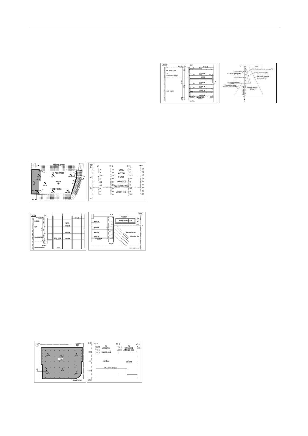
3.1 Site 1: S.P.S and ground anchor on C.I.P wall
Site 1 is the office facility of 7th floor on the ground and 3rd
floor in the basement. The building is located at Chung Ju in the
central region of Korea (Saegil E&C, 2011a). The excavation
depth is in the range of of GL.-14.0m~GL.-20.0m. High
apartments with deep parking lot are in the southern part of the
site. A building with basement is located 20m apart from the
site in the west. Roads of 35m and 23m are located at the north
and the east part of the site.
Two types of retaining walls are used, i.e. rigid C.I.P wall
and H-Pile & Timber. Ground anchor is used as the support of
both walls. Considering the tall buildings with basements, S.P.S
method is used at the southern part (Fig. 3).
The soil profile of the excavated site is composed of buried
soil layer, alluvial layer, weathered soil and rock layers from the
surface. Most of the excavated parts are composed of soils
(Fig.4). Two sections, i.e. S.P.S and ground anchor, are selected
as the analysis section in this paper (Fig. 5).
Figure 3. Plan view of site 1 Figure 4. Soil profile of site 1
a) Sec. A-A’ (C.I.P & S.P.S) b) Sec. B-B’ (C.I.P & Anchor)
Figure 5. Section view of Site 1
3.2 Site 2: S.T.D and C.I.P
Site 2 is the office facility of 23rd floor on the ground and 7th
floor in the basement. The building is located at Sang Am dong,
Seoul, Korea (Saegil E&C, 2011b). The excavation depth is in
the range of GL.-25.0m~GL.-31.0m. A building of 20th floor on
the ground and 5th floor in the basements is located to the north
of the site. In the east, the road of 30m wide and the building
with 21st floor on the ground and 7th floor in the basements is
located. The roads of 30m wide are located to the south and the
west directions.
The retaining wall is composed of C.I.P in the soil layer and
H-Pile & shotcrete in the rock layer. S.T.D method is used as
the support of the excavation site (Fig. 6).
Figure 6. Plan view of site 2 Figure 7. Soil profile of site 2
The soil profile of the excavated site is composed of buried
soil layer, weathered soil and rock layers, and soft rock layer
from the surface. The geotechnical investigation shows that the
soft rock appears at the shallow depth of GL.-2.4m and GL.-
9.2m (Fig. 7).
Figure 8. S.T.D Section A-A’ Figure 9. Schematic section for
Analysis Program
The sections of retaining walls, i.e. C.I.P in the soil layer and
H-Pile & shotcrete in the rock layer are selected for analysis.
S.T.D method is used as the supports of the excavated site (Fig.
8).
4 ANALYSIS PROGRAM FOR DESIGN
The program used in the design stage is SUNEX(Step UNder
ground EXcavation), which is a stress-strain analysis program
commonly used for the design of the deep excavation site in
Korea (Geogroup Eng., 2010). This program calculates earth
pressure on the braced earth retaining system, horizontal
displacement, shear force and bending moment of vertical wall
and axial force of supports and tieback anchors for step by step
excavation.
The program adopts elasto-plastic behavior of soil to
calculate earth pressure on the retaining wall. Calculation model
includes elastic beam for vertical wall (elastic-plastic beam
optional), elastic spring for strut and tieback anchor, elasto-
plastic spring for active and passive soil (Fig. 9).
5 COMPARISON OF DESIGN AND MONITORED
VALUES
Both the wall displacement and the axial stress of the struts
obtained either from the design stage using the SUNEX or from
the field monitoring using the field installed instruments. In this
section, The two values are compared by separating to the mid
and the final stage of the excavation.
5.1 Wall displacements
5.1.1 Site 1 : S.P.S and ground anchor on C.I.P wall
The displacements of wall in which S.P.S method is applied
are shown in Fig. 10 for the mid and final stages of excavation,
i.e. GL.-7.9m and GL.-16.5 m.
In the mid stage of excavation, the predicted design
displacement was 26.7mm and was greater about 20mm than
the monitored displacement of 7.0 mm. This discrepancy
seemed to come from the fact that the influence factors, e.g. the
loads behind the wall, the excavation height for installation of
supports, and weak soil profiles near the ground surface, were
selected conservatively compared with the real field conditions.
However, in the final stage the two values were come out
quite close. The reasons for this consistency are: (1) The
construction conditions was very similar to the one adopted in
the design stage, according to the construction process
identified at the site; (2) In S.P.S method, it is able to install the
steel supports immediately after the excavation. This gives an
advantage of reducing the time delayed displacement of the
wall, which developed the quite consistent displacements
between the design stage and the actual excavation.


