2009
Technical Committee 207 /
Comité technique 207
building pit. Based on CPT-measurements of the cone
resistance at a comparable building pit, it was assumed that the
relaxation amounts to 20% up to a distance of 12 m of the
building pit, and that the relaxation from this distance decreases
with 2.5% every 5 m. The decrease of the vertical bearing
capacity was assumed to be proportional to the relaxation of the
sand layer.
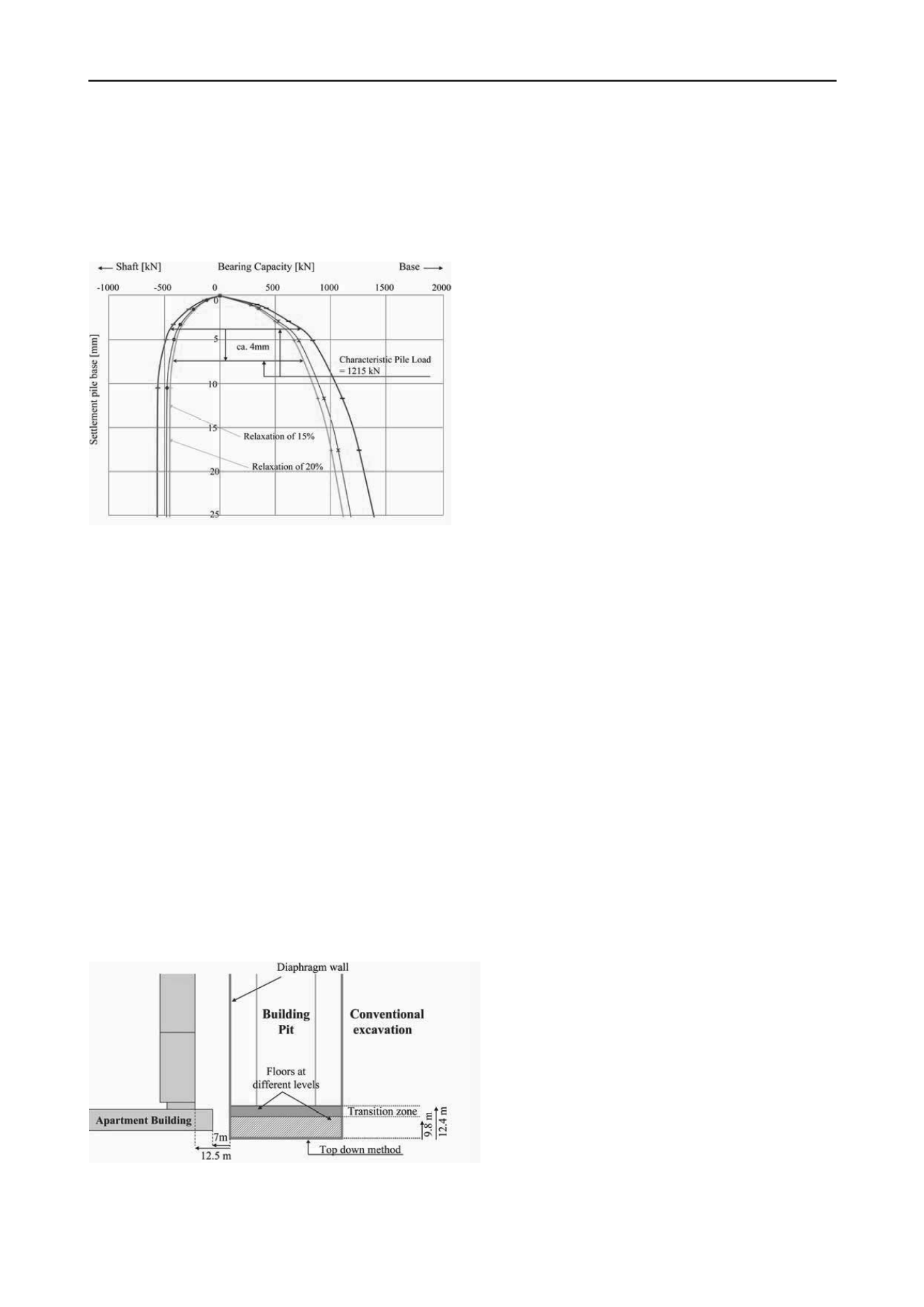
Figure 4. Graphical determination of the pile base settlement.
Load-settlement diagrams have been composed for the
serviceability limit state, based on NEN 6743-1 (see Figure 4).
For example, a pile base settlement of 4 mm is expected for the
original situation. Due to a relaxation of the sand layer of 20% a
pile base settlement of 8 mm is calculated, thus an additional
settlement of 4 mm as a consequence of the relaxation.
It was concluded that the piles 380 mm square could settle 2
to 4 mm as a result of a relaxation of the sand layer of 12.5 to
20%. For piles 450 mm square these values varied between 3.5
and 5 mm.
3.2
Horizontal soil displacement due to the deflection of the
diaphragm wall
The greenfield horizontal soil displacement at the position of
the relevant foundation piles of the apartment building has been
calculated by using the Hardening Soil (HS) model with the
Small Strain Stiffness (HSS), of the computer code Plaxis 2D
8.5. Three cross-sections were considered (see Figure 5):
- at the middle section of the building pit where the excavation
took place according to the conventional method;
- next to the apartment building, where the car park was built
according to the top down method: after the construction of the
diaphragm wall the roof is built, and after that the soil is
excavated below the roof and the successive floors are made;
- in the transition zone between the two building methods.
Horizontal displacements of the pile foundation, varying
between 10 and 25 mm, were also expected. Also no damage
was expected in this case, because the displacement would
manifest itself underground, with only a limited effect on the
foundation piles and the superstructure.
Figure 5. The cross-sections of the building pit that were considered
with the Plaxis 2D computer code.
The different stages of the excavation with the corresponding
lowering of the groundwater pressures in the building pit, and
the installation of the successive layers of struts have been
considered, and the displacements have been calculated. The
stiffness of the diaphragm wall was based on cracked concrete.
The calculated deflection of the diaphragm wall was about
70 mm in the middle section of the building pit, at a depth of 18
m. Next to the apartment building, the deflection was about 40
mm, at a depth of 20 m. The expected deflection of the
diaphragm wall was about 55 mm in the transition zone.
At the location of the first pile row of the apartment building,
the calculated greenfield horizontal soil displacement was 20
mm. At the following pile rows this displacement was
according to the calculations 10 to 15 mm.
From additional calculations with the elastoplastic spring
model of the computer code MSheet 7.7, it was concluded that
the expected moments and shear forces in the foundation piles
would remain smaller than the acceptable values.
3.3
Consequences of the soil displacement to the pile
foundation
The computer code Plaxis 3D Foundation 2.1 has been used to
determine the combined effect of the horizontal and vertical
ground displacements. With the computer code MFoundation
5.3.1.4 the vertical displacement was considered, and with the
computer code Plaxis 2D 8.5 the greenfield horizontal soil
displacement.
The diaphragm wall has been modeled from the southern
wall up to the middle of the conventionally built section. The
floors that are part of the section that was built according to the
top down method form part of the model. Only the five pile
rows next to the building pit, and the complete ground floor
were part of the model.
The piles were modeled as embedded piles. This made it
possible to determine the moments and shear forces as well as
the displacement of the foundation piles directly from the
calculations. The calculated settlements of the pile base may be
exaggerated, because the model does not take into account the
densification of the soil as a result of the installation of the
piles.
The with the computer code Plaxis 2D calculated deflection
of the different parts of the diaphragm wall was used to
calibrate the Plaxis 3D model. For the greater part of the
building pit the calculated maximum horizontal displacement of
the diaphragm wall was about 70 mm, in accordance with the
results of the calculations with the Plaxis 2D computer code.
Near the southern part of the diaphragm wall the calculated
displacement varied between 15 and 40 mm.
According to the calculations, the pile base of both the 380
mm pile, and the 450 mm piles will settle 8 to 12 mm as a
consequence of the soil displacement. The calculated horizontal
deflection of the foundation piles was 25 mm as a maximum.
The calculated moments and shear forces are relatively small.
4 PREDICTION
Based on the calculations the predicted settlement of the
apartment building was 2 to 5 mm due to relaxation and 8 to 12
mm due to the soil displacement. This means in total 10 to 15
mm as a consequence of the building activities for the
underground car park. Damage was not expected, because of the
decrease of settlement with distance from the building pit. The
settlement difference of the piles was expected to be small.


