2000
Proceedings of the 18
th
International Conference on Soil Mechanics and Geotechnical Engineering, Paris 2013
(
S
u
) was 13
kPa
as measured by lab shear vane method along
the tank depth.
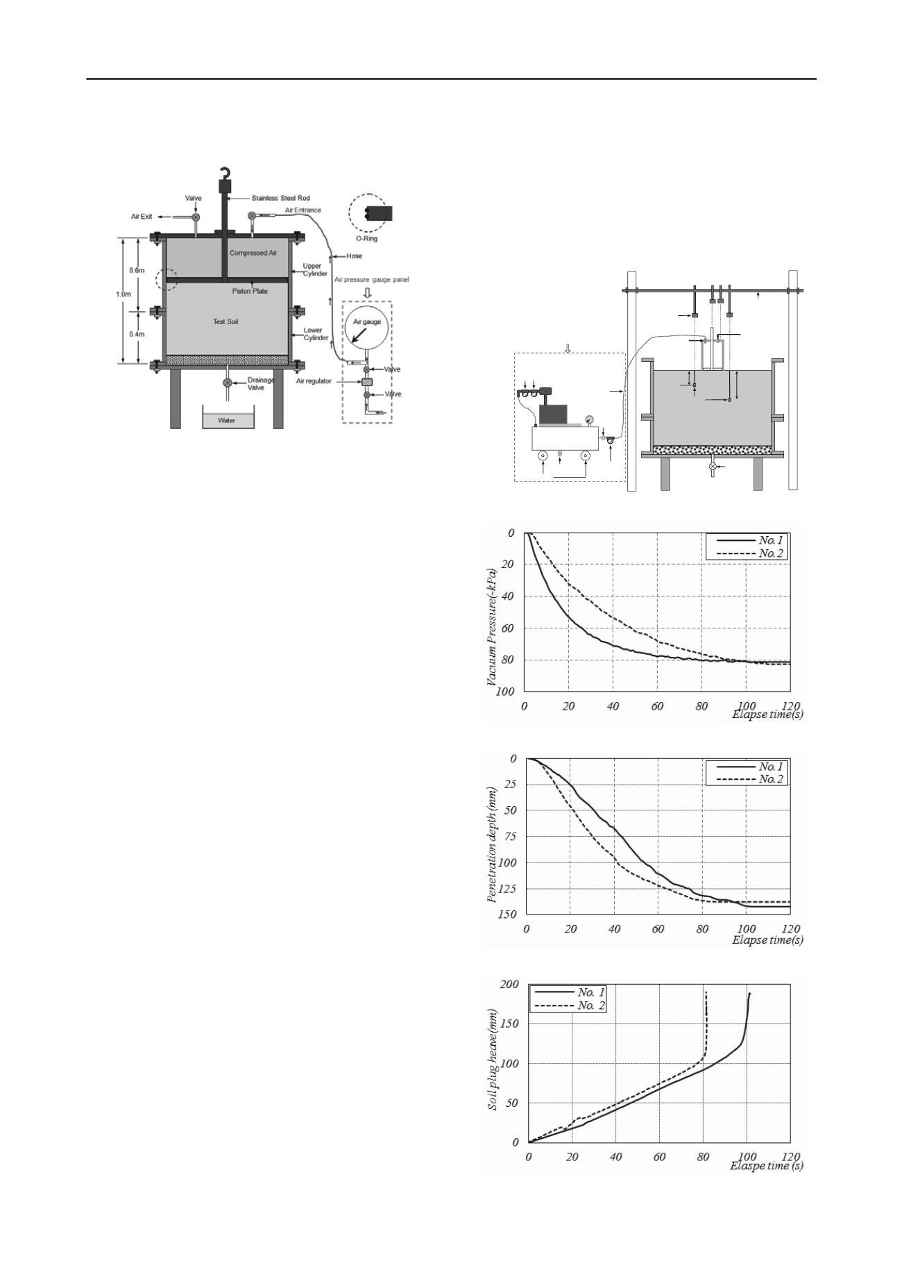
Figure 1 Consolidation procedure of kaolin
2.2 Caisson Installation
The caisson was made by an inner steel skirt and covered by a
layer of concrete with its total height of 400
mm
, diameter of
205
mm
and wall thickness of 22.5
mm.
The Caisson was
assembled with a designed piston which made it possible to
monitor the process of soil plug during installation tests. The
piston consisted of a ‘Teflon’ plate and a steel rod. The plate
was 25 mm thick and 150 mm in diameter with steel rod
mounted in the middle. A crew with a height of 20 mm was
used to strengthen the connection of the rod and the plate. Thus
the clear internal skirt length of the caisson reduced from
400
mm
to 335 mm. The total weight of caisson and piston was
27.2
kg
.
The vacuum loading system was composed by a vacuum
pump (EVISA E25), a vacuum gauge, two bowl vacuum filters,
a vacuum tank, and a hose, as illustrate in Figure 2. Note that
during suction installation tests, one more absolute pressure
transducer was mounted in the caisson cavity to test the vacuum
pressure.
The miniature pore water pressure transducers (PPTs) were
used in this model test to measure the pore water pressure
changes. Such a miniature size was necessary to minimize the
influence of the measuring device to the overall soil behavior
during model test. Before a model test, all PPTs were calibrated
by using water pressure generated in a triaxial cell. The
preinstalled positions of the PPTs on the top cap are shown in
Figure 2.
The displacement of the piston in the consolidation tank or
that of the suction caisson during the model test was measured
by laser sensor (KEYENCE IL series) which had an effective
measurement range from 20
cm
to 1.0
m
. The displacement of
piston rod in caisson was also measure by another laser sensor
by mounting an aluminum plate on to the rod. The third laser
sensor was mounted on the frame to measure the displacement
of suction caisson. Two other laser sensors were used to
measure the soil movement on caisson sides as shown in Figure
2. This contact-free displacement measuring method offered
both reliability and convenience.
2.3 Model Test Results
The model test results of caisson penetrated into the soil bed
assisted by vacuum pressure was discussed in this section. Since
the self-weight was not able to provide enough penetration force
for caisson insertion, the caisson was manually penetrated into
soil in a short distance to ensure that the applied suction would
not leakage. The applied vacuum pressures in Model Test
No. 1
and
No. 2
during the suction installation are shown in Figure 3.
It can be seen that the vacuum pressure increased very slowly
till to the largest magnitude of -80
kPa
. The displacements of the
caisson and soil plug are shown in Figure 4 and Figure 5,
respectively. It can be seen that the soil plug was moving
upward throughout the installation procedure. At the beginning,
the soil plugs increased nearly linearly with the time. A the time
of 81
s
for test
No. 1
and 96
s
for test
No. 2
, there was a sudden
jump in the displacement. This happened because the soil plug
was broken suddenly. During this period, the caisson had no
penetration.
PPTs
Laser sensor
8cm
20cm
Soil surface
Test Soil
Drainage Valve
Hose
Absolute pressure
Transducer
Air vent
Vacuum gauge
Vacuum
Pump
Bowl filter
Vacuum tank
Bowl filter
Wheel
Drainplug
Frame for laser sensors
Vacuum loading system
Air valve
Figure 2 Installation of suction caisson
Figure 3 Vacuum pressure vs. time curve
Figure 4 Penetration depth vs. time curve
Figure 5 Penetration depth vs. soil plug heave curve


