1998
Proceedings of the 18
th
International Conference on Soil Mechanics and Geotechnical Engineering, Paris 2013
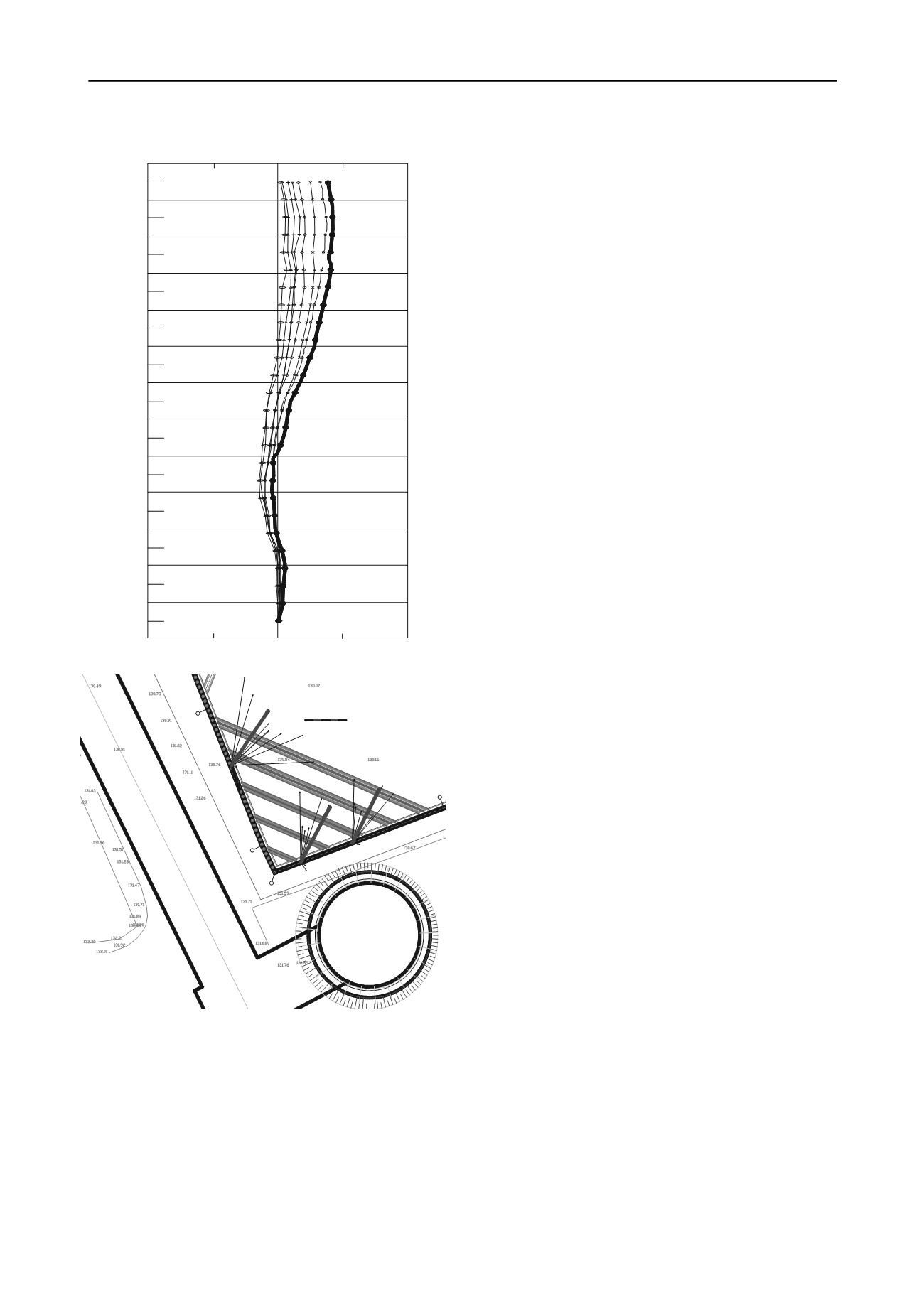
Figure 8. (a) Inclinometer (b) optic survey results
In addition to deformation monitoring, the axial forces (and
dependently stresses) on the steel struts were monitored by
means of strain-gauges. As expressed in Table 4, the maximum
axial force on the steel struts were found as 263 kN/m
(normalized axial force ~1500 kN). This value corresponds to a
stress value of ~125 MPa. The maximum axial force from the
strain-gauge readings is calculated as ~1620 kN corresponding
stress is calculated as 130 MPa. The mean axial deformation
horing wall was calculated as ~6.2 mm,
can be concluded Finite Element Analyses (preferably including
ically complex problems) are useful tools
Und
Geological
Characteristics of Istanbul Greywackes”, 10
th
IAEG2006, Paper
395, Nothingam, UK.
Undul O. and Tugrul A, 2006. “The Engineering Geology of Istanbul,
Turkey”, 10
th
IAEG2006, Paper 392, Nothingam, UK.
perpendicular to the s
which was derived from the results of axial compression values
(
L
17.5 mm) from the strain-gauges.
5 CONCLUSIONS
In the deep excavation project in Istanbul, geotechnical
dimensioning of the shoring system was defined by means of
Limit Equilibrium and Finite Element method of analyses. Both
2D and 3D FE analyses were adopted for evaluation of the
interaction between the adjacent tunnel & shaft (which were
still under construction and standing with their temporary
supports) with the deep excavation. The shaft and the tunnel
design had not foreseen the deep excavation at their close
vicinity, so the responsibility of ensuring the stability of the
excavation itself and of the tunnel and shaft was the sole
responsibility of the deep excavation support system designer.
Based on the results gathered from this project, it can be
concluded that the 2D FEA leads to safer results (slightly higher
deformation values and section forces) compared to 3D FEA.
This conclusion is also in accordance with our own expertise in
deep excavation design works with similar circumstances.
Moreover, the data gathered from the geotechnical
monitoring program revealed compatible in-situ performance
with the analyses results (both on deformations and stresses). It
3D FEA in geometr
under expertise whereby supported with in-situ monitoring.
6 REFERENCES
Güler F.E. and Bakilar G.S., 2008. “Related Geotechnical-Geological
Investigation Report”, Istanbul
“Periodic Geotechnical Instrumentation Reports of the site”, ELC
Group Inc., Istanbul
“Engineering Design Report of Pedestrian Tunnels and Shaft”, Yuksel
Proje International Inc., 2010, Ankara
O DIANA BV. V.9.4.3 “
TN
Users Manual Analysis Procedures”, Delft
PLAXIS BV. V.2D.2011 “Reference Manual”, Delft
ul O. and Tugrul A, 2006. “The Engineering
-15.0
0.0
15.0
0.0
2.0
4.0
6.0
8.0
10.0
12.0
14.0
16.0
18.0
20.0
22.0
24.0
26.0
(a)
A
B
N
M
B'
Tip-AStrut
Tip-BStrut
Tip-CStrut
Tip-DStrut
Tip-EStrut
B5
B3
B2
2
1
2
1
2
1
0 mm
1 mm
2 mm
3 mm
5 mm
4 mm
3
3
5
7
7
8
8
8
9
9
9
10
10
10
11
11
12
12
12
13
13
13
Latest
Latest
Latest
6
Maximumdfr. at shaft location : ~7mm
Maximumdfr. at tunnel location : ~8mm
(b)


