1997
Technical Committee 207 /
Comité technique 207
displacements) are presented in this paper (both from 2D FEA
and 3D FEA) in Table 3. The given results for the tunnel and
shaft structures are values prior to excavation and final values
after completion of deep excavation work.
Table 3. Results of FEA
Result
2D FEA
3D FEA
Deformation of shoring (mm)
7.8
4.2
Deformation of Tunnel (mm)
9 / 3
2.0
Deformation of Shaft (mm)
NA
3.2
Bnd.Moment on Shoring (kNm/m)
97.3
31
Bnd.Moment on Tunnel (kNm/m)
9 / 16.4
8.4 / 8.7
Bnd.Moment on Shaft (kNm/m)
NA
13.9 / 16.1
Shear Force on Shoring (kN/m)
132.4
83
Shear Force on Tunnel (kN/m)
20.2 / 22.5
26.8 / 25.3
Shear Force on Shaft (kN/m)
NA
20.0 / 19.6
Normal Force on Shoring (kN/m)
416.8
366
Normal Force on Tunnel (kN/m)
470.7 / 633.4
545 / 532
Normal Force on Shaft (kN/m)
NA
800 / 666
The result for total deformation from the 3D FEA is
presented in Figure 4. The result for total deformation from the
2D FEA is presented in Figure 5.
Figure 4. Total displacement from 3D FEA (max. 4.2 mm)
Figure 5. Total displacement from 2D FEA (max. 7.8 mm)
The result for bending moments (on all shell elements) is
presented in Figure 6.
Figure 6. Bending moments from 3D FEA (max. 31 kNm/m
shoring, max. 8.7 kNm/m tunnel, max. 16.1 kNm/m shaft).
In addition to deformations and section forces, the axial
forces on the steel struts are also calculated and compared with
both 2D and 3D FEA. The values are presented (as the envelope
values for all construction and demounting stages) in Table 4.
Table 4. Results of Axial Forces in struts
Result
2D FEA
3D FEA
Axial Forces (kN)
263 kN/m
627-765 kN*
*
The assumed length of struts in 2D is 20 m hence the results
of 17-23 m struts in 3D model are given. The spacing of the
struts in 2D model is 4.0 m, so that the value of 263 kNm/m
(perpendicular to the surface) shall be multiplied by 3 in order
to get the axial perpendicular force of an individual strut.
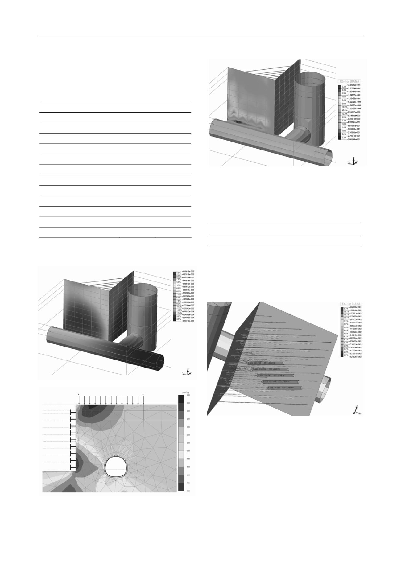
The results for steel strut axial forces from 3D FEA are
presented in Figure 7.
885 kN
838 kN
765 kN
627 kN
219 kN
Figure 7. Total strut forces from 3D FEA (max. 885 kN)
4 CONSTRUCTION AND MONITORING PHASE
During construction period, a geotechnical instrumentation
program, consisting of inclinometers, optic survey points (for
deformation monitoring) and strain-gauges (for axial force and
dependently stresses on steel struts), has been carried out. This
monitoring program gave reliable data and so it was possible to
verify the design results with in-situ performance that has been
gathered.
The maximum deformation on the inclinometer at shaft
location (INK-07) was measured as ~7 mm. The maximum
deformation values received from optical surveys are also ~7
mm at shaft location and ~8 mm at the tunnel location.
Inclinometer and optic survey results are presented in Figure 8.


