1990
Proceedings of the 18
th
International Conference on Soil Mechanics and Geotechnical Engineering, Paris 2013
\
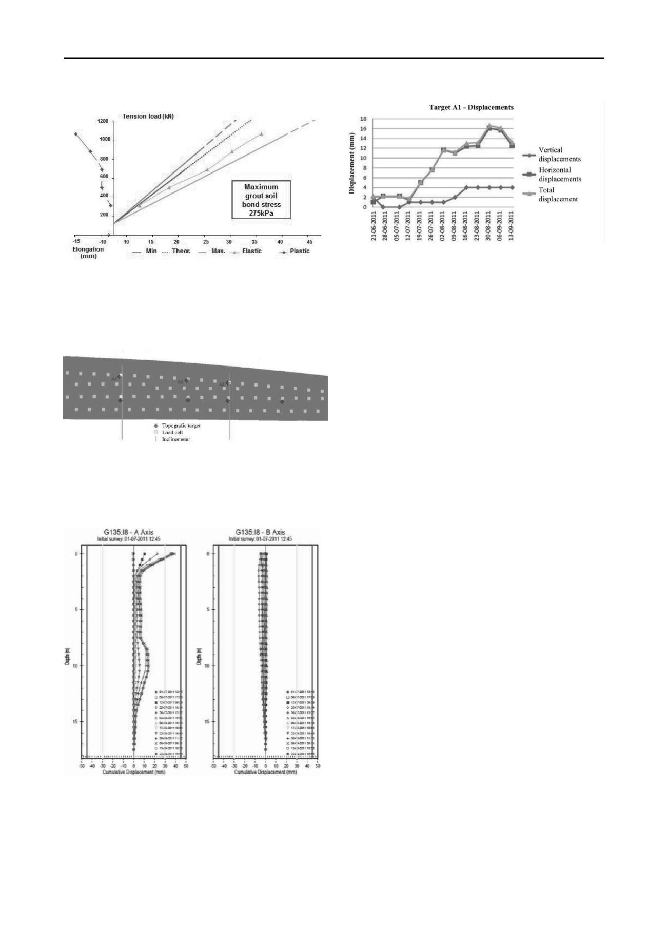
Figure 12. Displacement recorded at the topographic target A1.
Figure 9. Main results of the ground anchor suitability test
.
6 MAIN CONCLUSIONS
5 CSM WALL PERFORMANCE
The implemented monitoring and observation plan, is shown on
Figure 10, including 2 inclinometers and 7 topographic targets.
The case study presented in this paper shows the good
performance, mainly low deformations, of an anchored
retaining structure, combining CSM panels with a reinforced
concrete lining wall, leading to the optimization of both the
construction overall schedule and budget in a complex
geotechnical and site conditions. It was also shown that the use
of commercial FEM software with appropriated input data gives
a reasonable prediction of the main displacements, which are
critical for the verification of both the ultimate and
serviceability limit states, for all the excavation phases.
Figure 10. Monitoring and observation plan.
7 ACKNOWLEDGEMENTS
Figure 11 shows that the maximum displacement was
observed at 10 m depth, corresponding to 15 mm (inclinometer
I8).
The authors wish to thank to “Fundação para a Ciência e a
Tecnologia” (FCT) for the financial support under the strategic
project PEst-OE/ ECI/UI4047/2011. In addition, the authors
would like to thank the contribution of Ângelo Pereira.
8 REFERENCES
Ameratunga J.; Brown D.; Ramachadran R.; Denny R. (2009). “Ground
improvement for a large above ground storage tank using cutter soil
mixing columns.”
Proc. 17th International Conference on Soil
Mechanics and Geotechnical Engineering
, Alexandria, Egypt, pp.
2280-2283.
Bruce D.A. 2000. An introduction to the deep soil mixing methods as
used in geotechnical applications.
Federal Highway Administration
,
Georgetown.
Capelo A., Gomes Correia A., Ramos L.R., Pinto A. And Tomásio R.
2012. Modeling and monitoring of an excavation support using
CSM.
4th International Conference on Grouting and Deep Mixing
,
New Orleans, Louisiana, USA, ASCE, GSP (in printing).
Larsson S. 2003. Mixing processes for ground improvement by deep
mixing.
Department of Civil and Environmental Engineering,
Royal Institute of Technology in Stockholm
.
Marzano I.P., Osman A.A-M., Grisolia M., Al-Tabbaa A. 2009.
Mechanical performance of different stabilised soils for application
in stratified ground.
17th International Conference on Soil
Mechanics and Geotechnical Engineering
, Alexandria, Egypt, pp.
2276-2279.
Pereira A. 2011.
Application of Cutter Soil Mixing Technology in
containment of a retaining wall anchored linear
. MSc dissertation,
Guimarães (in Portuguese).
Figure 11. Displacement recorded at the inclinometer I8.
In Figure 12 it is observed that the maximum vertical
displacement is 4 mm and that the maximum horizontal
displacement is 17 mm.
These results show that the FEM analysis, with the presented
input data, has given a good analytical prediction of the
observed horizontal displacement, mainly confirming the depth
where the maximum horizontal displacement occurred.
Pinto A., Tomásio R., Pita X., Pereira A. and Peixoto A. 2011. Cutter
Soil Mixing Solutions in Portugal on Hard Soils and Weak Rocks.
Proc. 15th European Conference on Soil Mechanics and
Geotechnical Engineering
, September 2011, Athens, Greece, Part 2
– 3.3 – Ground Reinforcement, pp. 1037–1042.
Pinto A., Tomásio R., Godinho P., 2013. Innovative Solution of King
Post Walls combined with CSM.
Proc. 18th European Conference
on Soil Mechanics and Geotechnical Engineering
, Paris, France.
Porbaha, A. (2000). State of the Art in Deep Mixing Technology. Part
IV: Design Considerations.
Ground Improvement
, 4(3), 111–125.


