1984
Proceedings of the 18
th
International Conference on Soil Mechanics and Geotechnical Engineering, Paris 2013
Proceedings of the 18
th
International Conference on Soil Mechanics and Geotechnical Engineering, Paris 2013
1 ANALYTICAL APPROACH OF A L-SHAPED WALL
WITH A RELIEF FLOOR
The envisaged geotechnical structure is an inverted T-shaped
cantilever wall with a relief floor. Figure 1 shows a typical
section of this construction with a retaining soil height of 8.6m.
The foundation level is 0.8m below ground surface, in order to
place it under the frost line. In order to study the behavior of
this structure, a brief review of the behavior of L-shaped
cantilever walls and the influence of a relief floor is given,
before the global analytical approach is proposed.
Figure 1. View of the inverted T-shaped cantilever wall with a relief
floor of 3.9 m.
1.1
Geotechnical principle of L-shaped cantilever wall
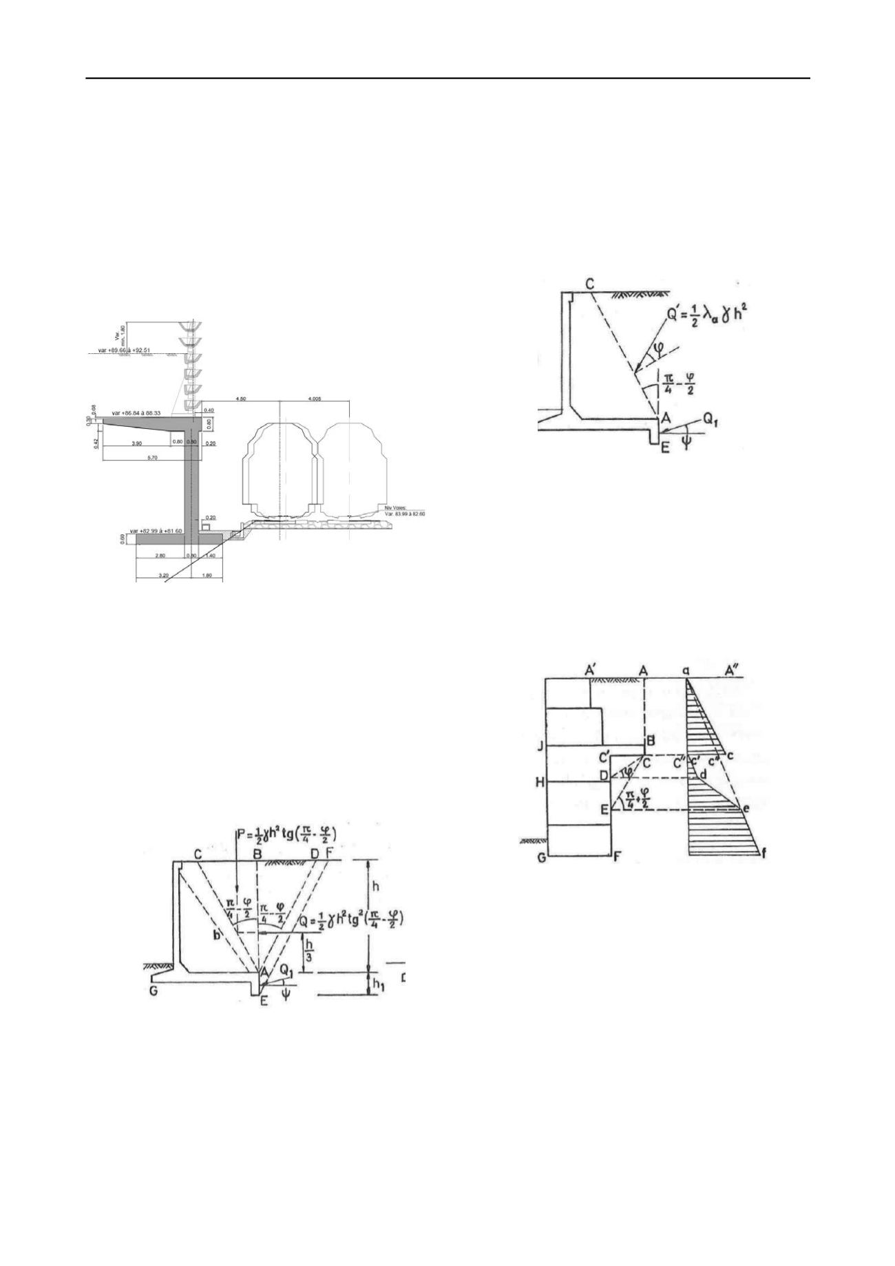
The geotechnical behavior of a L-shaped or an inverted T-
shaped cantilever wall is quite complex (Figure 2). When the L-
shaped wall fails geotechnically, the failure surfaces E-F, A-D
and A-C occur. All these failure surfaces have an inclination of
π/4
-
φ/2
from the vertical A-
B (further called ‘virtual back’).
All
the soil in the block A-C-D can be described as active Rankine
soil. The block A-C-F-E deforms and slides downwards
simultaneously. The soil pressure distribution in the block A-C-
D is symmetrical about the vertical A-B, on which horizontal
soil pressures are present. This theory is confirmed by
numerical modeling (e.g. Arnold, 2010).
Figure 2. Soil rupture surface (wing shape : C-A and E-F) of a L-
shaped cantilever wall (after Vandepitte, 1979).
It is shown that this complex geotechnical behavior of the L-
shaped or an inverted T-shaped cantilever wall is equivalent to
the following simplified structure (Rouili et al. 2005;
Vandepitte 1979). The wall together with the backfill up to a
vertical plane above its heel (A-B
i.e. ‘virtual back’) is treated
as a monolithic block. Gravity forces, surface loads and
horizontal active soil pressures acting at the virtual back may be
assumed. This block is checked against sliding, overturning and
bearing capacity failures in the ultimate limit state (GEO 2000;
Frank et al. 2004).
This approach is mathematically equivalent to the
consideration of the wall together with the backfill up to the
plane A-C (Figure 3).
It has to be stressed that though the two above approaches
are equivalent for the design of the L-shaped or an inverted T-
shaped cantilever wall, the wing-shaped soil rupture surface is
the only physical failure mode.
Figure 3. Alternative design rupture surface C-A-E of a L-shaped
cantilever wall (after Vandepitte, 1979).
1.2
Geotechnical principle of a relief floor
Geotechnical constructions sometimes uses a relief floor. If the
relief floor is rigidly build-in in the geotechnical construction, it
implies three stabilizing effects (Figure 4):
1.
the backfill in the area A’
-A-B engenders a stabilizing
moment against overturning,
2. a reduction of the total horizontal soil pressure,
increasing the safety to sliding,
3. a reduced eccentricity of the global force at the base,
increasing the bearing capacity.
Figure 4. Four zones of soil pressure distribution A-
C, C’
-D, D-E
and E-F. (after Vandepitte, 1979).
Four zones of horizontal soil pressure can be distinguished:
Zone 1 : A-C is not influenced by the relief floor.
Zone 2 : C’
-D is totally influenced by the relief floor. The
horizontal soil p
ressure is 0 in C’.
Zone 3 : D-E is partly influenced by the relief floor. The
horizontal soil pressures increases linearly from d to e.
Zone 4 : E-F is not influenced by the relief floor. The
horizontal soil pressure correspond to the active soil pressure,
taking into account the surface level A’A and the present
surface load.
1.3
Simplified analytical approach of an inverted T-shaped
cantilever wall with a relief floor.
The proposed simplified analytical approach combines the
theory of the L-shaped cantilever wall and the theory of the
relief floor. Two virtual backs are defined : upper virtual back
A-
B and lower virtual back C’
-F (Figure 5).


