1986
Proceedings of the 18
th
International Conference on Soil Mechanics and Geotechnical Engineering, Paris 2013
Proceedings of the 18
th
International Conference on Soil Mechanics and Geotechnical Engineering, Paris 2013
2.3
Comparison of the numerical simulation with the
proposed analytical approach
The inverted T-shaped cantilever wall with a relief floor in § 3.2
is compared with the analytical calculation as described in §2.3.
The geometry and the soil parameters are similar inputs in both
approaches.
Remember that the analytical calculations consider active
soil pressures. Therefore, the analytical approach assumes a
displacement of the structure. In the numerical simulations, this
displacement of the structure occurs only in stage 5 ‘c
-phi-
reduction’. When forces in the analytical calculations are
compared to those in the c-phi reduction stage of the numerical
s
imulations, it is important to notify that the actual cohesion c’
and angle of internal friction of the soil φ’ are reduced.
In the analytical approach, the factor of safety is 3,39 for the
overturning failure mode, 1,98 for the sliding and 2,14 for the
bearing failure mode. Figure 7 suggests that the failure mode of
the numerical model is the bearing capacity (c-phi reduction
safety factor = 1,20).
Table 2 shows that the difference of the horizontal forces at
the virtual backs in the analytical approach and in the numerical
simulations is below 8%. The difference of the vertical force at
the foundation amounts to 15%.
Table 2. Comparison of the horizontal and vertical forces at the virtual
backs and the foundation in the analytical approach and the numerical
simulations.
Anal. approach
Num. simulation
Horizontal force at
upper virtual back
57
kN/m’
62
kN/m’
Horizontal force at
lower virtual back
230
kN/m’
211
kN/m’
Vertical force at
foundation
951kN/m’
1117
kN/m’
3 PREDESIGN OF L-SHAPED CANTILEVER WITH
RELIEF FLOOR
Based on experience, numerical modeling and hand
calculations, typical dimensions of reliable inverted T-shaped
cantilever walls with a relief floor could be estimated. For sandy
soil and a buried depth of 0,8m and 1,3m; the L1 is about 20%
to 40% of the retained soil height H; the Fs (as defined in Figure
5) is about 1,5 to 2,5 m (Figure 8).
The level of the relief floor is of less importance for the
geotechnical design, as long as the full stress relief is applied on
the virtual back of the inverted T-shaped wall. Furthermore, it is
good practice to design the level of the relief floor at about the
half of the retained soil height.
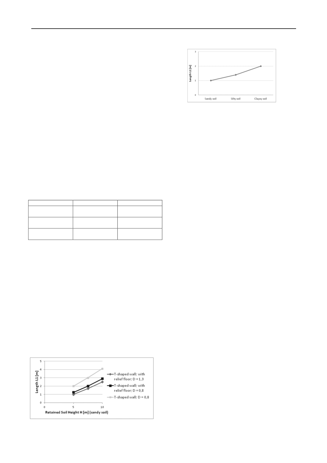
The type of soil in situ is an important geotechnical
parameter, specially for the bearing capacity and sliding failure
mode. For inverted T-shaped walls with relief floor, retaining a
soil height of 5 m, a buried depth D = 1,3m; the length L1
varies from 1m (sandy soil) to 2m (clayey soil) (Figure 9).
Figure 8. Typical distance between the front of the stem and the
back of the heel (L1 [m]) of inverted T-shaped cantilever walls with and
without relief floor in sandy soils.
Figure 9. Typical distance between the front of the stem and the
back of the heel (L1 [m]) of inverted T-shaped cantilever walls with a
relief floor in sandy, silty and clayey soils (retained soil height of 5,0m;
buried depth of base slab D = 1,3).
4 CONCLUSIONS
The geometry of an inverted T-shaped cantilever wall with a
relief floor depends on the height of the retaining soil, the
surcharges, the depth of the foundation base slab, the
geotechnical parameters of the soil in situ and of the backfill,
the possible length of the toe and so forth.
In the case of unsaturated sandy soils, silty soils and alluvial
clayey soils, an analytical approach is proposed and confirmed
by numerical simulations. The analytical approach is based on
an upper and a lower vertical virtual back. The wall together
with the backfill up to the virtual backs are treated as a
monolithic block. At the lower virtual back, the horizontal soil
pressures are reduced, due to the presence of the relief floor.
This monolithic block is checked against sliding, overturning
and bearing capacity failures in the ultimate limit state.
For predesign estimations, a typical inverted T-shaped
cantilever wall with a relief floor may be considered:
the distance between the front of the stem and the
back of the heel is about 20% to 40% of the
retaining soil height,
the length of the toe is similar to the length of the
heel,
the base slab is buried deeper than the frost line,
the difference between the length of the relief floor
and the length of the heel is about 1,5m to 2,5m,
the level of the relief floor is about the half of the
retained soil height.
Though some general rules of thumbs for the dimensions of
an inverted T-shaped cantilever wall with relief floor are given,
each realization must be based on thorough geotechnical
evaluation of its design, a hydrogeological evaluation, a detailed
structural design, an analyses of the construction methodology
and a general risk evaluation.
5 REFERENCES
Arnold M. 2010. Physical modeling of L-shaped retaining walls.
Physical Modeling in Geotechnics
, Proceedings of the 7
th
International Conference on Physical Modelling in Geotechnics
(ICPMG 2010) 425-430 Zurich.
Brinkgreve R., Al-Khoury R., Bakker K., Bonnier P., Brand P., Broere
W., Burd H., Sotys G., Vermeer P. and Haag D. 2002.
Plaxis -
finite element code for soil and rock analyses. User’s manual Ver.
8.0.
A.A. Balkema, Rotterdam.
Frank R., Bauduin C., Driscoll R., Kavvadas M., Krebs Ovesen N., Orr
T. and Schuppener B. 2004.
Designers‘ Guide to EN 1997
-1
Eurocode 7 : Geotechnical design
–
General rules
. Thomas
Telford, London.
GEO
–
geotechnical engineering office. 2000.
Guide to retaining wall
design
. Hong Kong.
Rouili A., Djerbib Y. and Touahmia M. 2005. Numerical modeling of
an L-shaped very stiff concrete retaining wall.
Sciences &
Technique
24 (B) 69-74.
Vandepitte D., 1979.
Berekening van constructies
. Scientia, Genth. (in
Dutch).


