1976
Proceedings of the 18
th
International Conference on Soil Mechanics and Geotechnical Engineering, Paris 2013
supra-glacial environment, which include glaciolucustrine clays
and melt-out and flow tills (Chung and Finno, 1992). Because
of this complicated depositional environment, the Blodgett
generally has variable geotechnical characteristics, including
water content, strength and stiffness. A desiccated crust is often
present on top of the Blodgett stratum. At these sites, the crust
is relatively thin, and in some cases is not present at all.
Underlying the Blodgett stratum is a medium stiff clay, called
the Deerfield stratum. This stratum exhibits much more
uniform geotechnical characteristics than the Blodgett because
the Deerfield was deposited as a basal melt-out till or a
waterlain paratill. The stiff Park Ridge clay underlies the
Deerfield layer. It is generally a little more overconsolidated
than the upper clays, with an OCR of about 1.5. A deposit
locally known as “hardpan” is found beneath the Park Ridge
stratum. The soils in the hardpan are very stiff to hard and
consist of silty clays to clayey silts and contain occasional
lenses of sandy soils. These soils are basal tills and
overconsolidated.
Figure 1. Subsurface conditions
3 BLOCK 37 PROJECT
Lateral support for the Block 37 excavation consisted of a 0.9 m
thick reinforced concrete slurry wall and four levels of
reinforced concrete floor slabs. After installation of the slurry
wall, existing foundations from previous buildings were
removed. These potholing activities were extensive near the
north end of the excavation, and excavations reached as deep as
6 m. After the abandoned foundations and walls were removed,
the excavations were backfilled.
Thereafter the excavation progressed in stages to the levels
of the four basement floors (B1, B2, B3 and B4). Because the
“ground” slab was placed after slab B1, the slurry wall was
cantilevered with an unsupported length of about 7 m before
any lateral support was placed. Thus this excavation deviated
from an ideal top-down construction system because the lateral
support was not installed prior to any significant excavation.
The contractor made the decision to delay placement of the
ground surface slab on the basis of construction expediency. A
complete description of the activities at the site and
performance of the excavation is found in Kern (2011).
3.1
Ground movements during construction
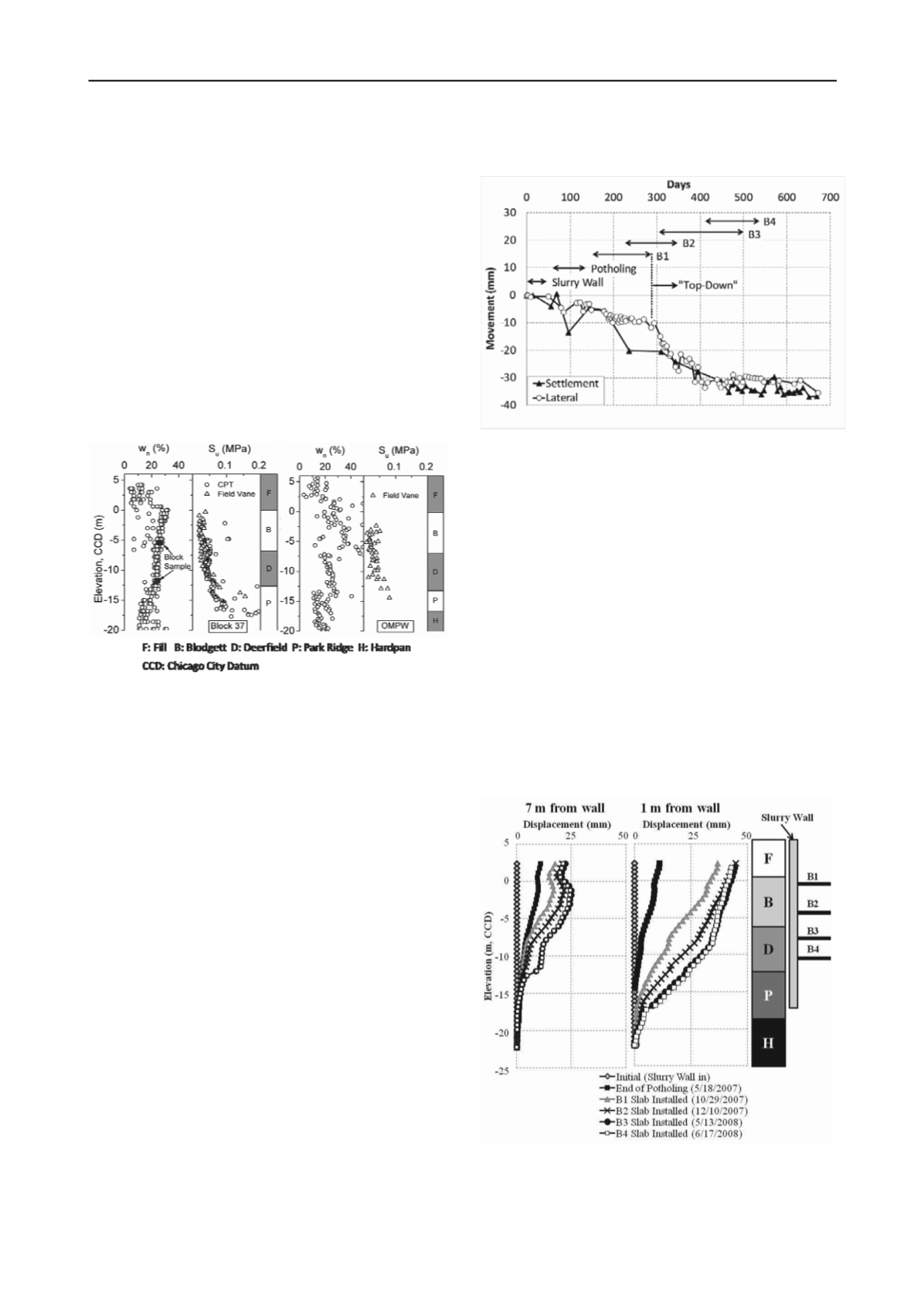
The development of ground movements during construction is
summarized in Figure 2. The optical survey points and
inclinometer were located adjacent to the north wall of the
excavation. The settlements are typical of the maximum values
measured along this side of the excavation. The horizontal
movements were taken from an inclinometer located 1 m behind
the slurry wall near its center and were taken from elevation – 9
m CCD. Lateral movements versus depth will be discussed in
the next section. Also shown on the figure is a record of the
construction activities so the causes of the movements are
apparent.
Figure 2. Settlements and lateral movements at Block 37
The maximum settlement and lateral movement observed at
this section was 36 mm. As is apparent from the figure,
significant ground movements developed during both the
potholing activities and the first portion of the excavation when
the large cantilever stage existed as the contractor excavated to
the B1 slab level. These activities caused about 60% of the
settlements that developed throughout the entire construction
process. This large percentage was caused by the contractor’s
decision to start the top-down process after the first level
basement was constructed. The removal of the old foundations
and slabs also contributed to the relatively large movements
observed along this wall.
3.2
Lateral movements adjacent to wall
Typical distributions of lateral ground movements with depth
are shown in Figure 3 for inclinometers located 1 m and 7 m
from the wall. These inclinometers were installed prior to any
construction at the site and thus indicate the complete lateral
response. The large influence of the potholing and initial
cantilever stage of the excavation is seen clearly in the results.
Figure 3. Lateral ground movements at Block 37
4 ONE MUSEUM PARK WEST PROJECT.
The One Museum Park West project involved constructing a
53-story reinforced concrete tower with a central core and four
or five basement levels that extended approximately 15.3 m


