1968
Proceedings of the 18
th
International Conference on Soil Mechanics and Geotechnical Engineering, Paris 2013
sea level and maximum excavation depth is approximately
24 m.
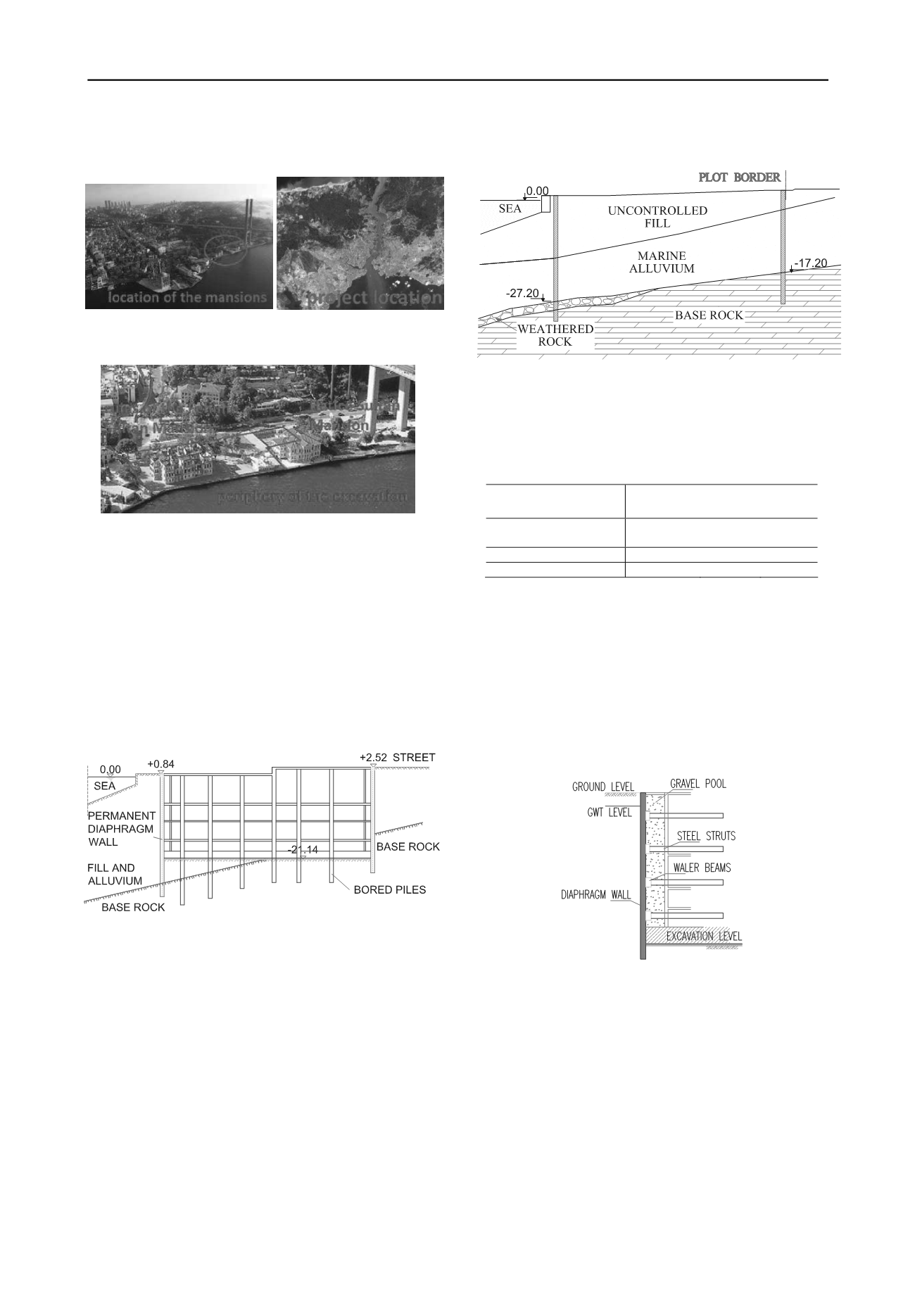
Figure 1a and 1b. General View of the Site Figure and Location of the
Site in Istanbul
Figure 2. Periphery of the Excavation (photo after the fire of 2002 and
before the start of the restoration campaign)
During the bidding stage, top-down construction proposed
by the foundation subcontractor was considered as a suitable
method under the existing conditions. Typical cross section of
the basement structures through the perpendicular direction to
the seashore is given in Figure 3. It is planned to use the
diaphragm walls as permanent periphery walls of the basement
floors, construct the bored piles as permanent columns of the
underground structure and integrate the foundation and slabs
with the permanent wall and columns during the top-down
construction method. This choice resulted in the necessity to
develop special details for ground water isolation and continuity
of the structural elements.
Figure 3. Section of the Basement Structure in Perpendicular to the
Seashore
3 GEOTECHNICAL MODELLING
Within the soil investigations ten boreholes were implemented
with a maximum length of 50 m. Two of the boreholes adjacent
to the seaside were implemented with 45° inclination and length
of these boreholes was 100 m. Also within the geophysical
measurements, MASW and microtremor studies are
implemented in the site to obtain the geodynamic modeling of
subsoils.
Soil profile consists in sequence from top to down as of
uncontrolled fill, marine alluvium and bedrock. Dyke, sandstone
and shale are the commonly encountered rock types at the site.
According to the results of vertical boreholes at the site bedrock
is located between 13.50 m and 27.20 m under the sea level.
Therefore length of the diaphragm wall and bored piles are
chosen variable from one location to another in accordance to
encountered bedrock elevations. Typical soil profile is given in
Figure 4.
Figure 4. Typical Soil Profile
Simplified average drained shear parameters of the alluvial
soil layers based on the field and laboratory testings are given in
Table 1. Ground water table is located within 1.0m to 3.0m
below the ground surface.
Table 1. Soil Properties
Layer
γ(kN/m³)
Ø’ (°)
c’
(kN/m²)
Uncontrolled Fill
and Marine Alluvium
18
28
1
Weathered Rock
22
33
20
Bedrock
24
33
50
4 PRELIMINARY DESIGN
The preliminary retaining system has been proposed by a
geotechnical design group employed by the Client prior to the
tender, which consisting a peripheral diaphragm wall and
tubular steel struts. Diaphragm wall thickness was considered as
800 mm and planned to be used only temporarily during the
excavation. To support the diaphragm wall, four rows of steel
struts are proposed to be implemented. The spacing between the
struts was 5.0 m in vertical and 8.20 m in horizontal directions.
Typical cross section of the tender design is given in Figure 5.
Figure 5. Tender Design Typical Cross Section
Complete underground structure were planned to be
constructed 21.20 m below the water table. As a result, the
uplift of the underground structure is one of the critical issues
for the design.
5 PROPOSED ALTERNATIVE DESIGN
During the bidding stage the applicability towards the
construction of underground structure and the cost of the tender
design was examined. One of the drawbacks realized was that
the space between the steel tubular struts was very limited to
implement the excavation works in a safe and efficient manner.
As a result, alternative top-down construction method was
proposed to eliminate the implications of steel struts. Further, in
order to eliminate the gravel filled between the walls; namely


