1962
Proceedings of the 18
th
International Conference on Soil Mechanics and Geotechnical Engineering, Paris 2013
The mechanical behaviour of reinforced soil walls is
complicated due to the mechanical complexity of the
component materials, their interactions, wall geometry and soil
type/arrangement, in addition to the unquantifiable effects of
construction method and quality. Nevertheless, current design
methods are typically based on classical notions of soil and
reinforcement ultimate strength. Furthermore, internal stability
design using conventional analytical solutions assumes that the
compressibility of the foundation soil does not influence
reinforcement loads.
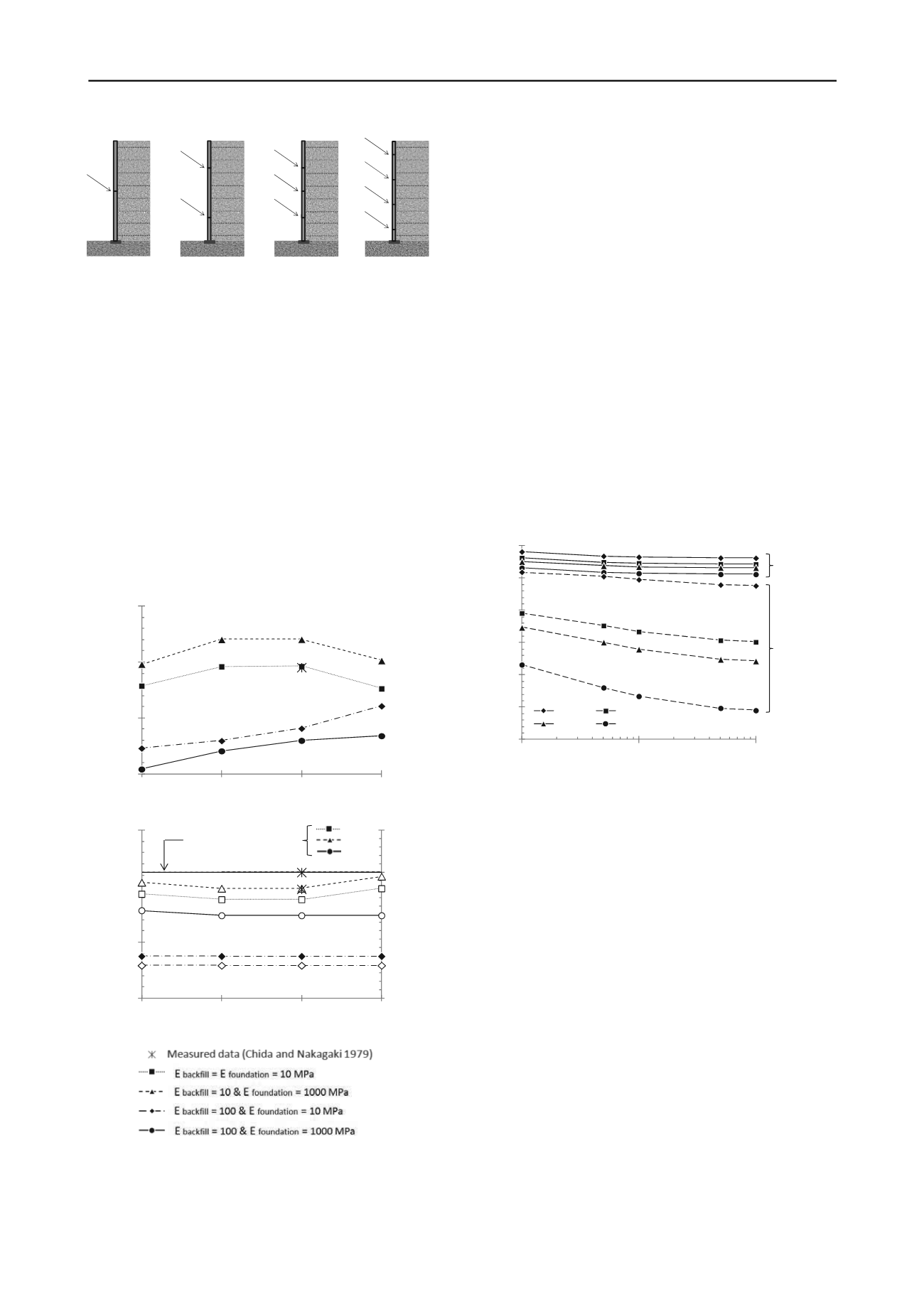
Figure 4. Schema about the horizontal joint options considered
2panels:
3m-higheach
1 joint
2 joints
3 joints
4 joints
4panels:
1.5m-higheach
(basecase)
5panels:
3units of 1.5 m-highand
2units of 0.75m-high
3panels:
2units of 1.5 m-highand
1units of 3 m-high
Figure 6 shows the effect of the foundation stiffness and the
vertical facing stiffness on the total vertical loads at base of the
facing. Three additional foundation stiffness cases are
considered here in order to obtain more data points. It can be
observed that higher values of the foundation stiffness (elastic
modulus) generate lower values of the total vertical load under
the facing. If the total vertical load under the facing with respect
to the number horizontal joints is analyzed (Figure 6), a
significant influence of the vertical facing stiffness on the
results can be noted. This influence is less relevant if the lowest
modulus of the backfill soil is assumed (i.e. E
backfill
= 10 MPa,
which generates a range of about 3 kN/m between boundary
cases). If the backfill soil is assumed with higher stiffness value
(E
backfill
= 100 MPa), the variation of the vertical load is more
significant with a range of 15 kN/m for the single joint case, and
20 kN/m for the four joint case.
The numerical simulation results in the current study
demonstrate, first, that vertical loads at the base of the facing
are affected directly by the backfill and foundation stiffness
scenario and the soil-facing interface shear strength; second,
there is a significant variation of reinforcement tensile load
results depending on the combination of the backfill and
foundation stiffness values; and third, the vertical stiffness of
the facing (represented by the number of horizontal joints along
the facing, that can be also be understood as different
thicknesses of the bearing pad elements) produce significantly
different effects on the vertical facing load and the
reinforcement tensile loads. These three outcomes cannot be
predicted for walls under operational (working stress)
conditions using current strength-based design methods for the
calculation of reinforcement loads.
35
40
45
50
55
60
65
10
100
1000
1 joint
2 joints
3 joints
4 joints
E
foundation
(MPa)
Verticalfacing toe‐load (kN/m)
E
backfill
E
backfill
=
10 MPa
=
100 MPa
24.5
15
20
25
30
1
2
3
4
Number of joints
T
maximum
(kN/m)
1.13
0.46
0.2
0.3
0.4
0.5
0.6
0
0.5
1
1.5
1
2
3
4
Number of joints
same strip elevation for
Wall elevation (m)
(closed symbols)
Normalized distance to the facing
(open symbols)
Figure 6. Vertical facing toe-load comparison with facing, foundation
and backfill stiffness
5 REFERENCES
Chida, S. and Nakagaki, M. 1979. Test and experiment on a full-scale
model of reinforced earth wall.
Proceedings of the International
Conference on Soil Reinforcement
, Paris, France, Vol. 2, pp. 533-
538.
Damians, I.P., Bathurst, R.J., Josa, A., Lloret, A. and Albuquerque,
P.J.R. 2013. Vertical facing loads in steel reinforced soil walls.
ASCE Journal of Geotechnical & Geoenvironmental Engineering
(in press).
Neely, W.J. and Tan, S.L. 2010. Effects of second order design factors
on the behaviour of MSE walls. Earth Retention Conference 3.
Earth Retaining Structures Committee of the Geo-Institute of
ASCE. Geotechnical Special Publications (GSP) n. 208.
Proceedings of the 2010 Earth Retention Conference
, Bellevue,
Washington, August 1-4, 2010, pp. 522-530.
PLAXIS. 2008. Reference Manual, 2D - Version 9.0. PLAXIS B.V.,
Delft University of Technology, The Netherlands.
Figure 5. Maximum reinforcement loads (T
max
) with respect to the
number of horizontal joints and backfill-foundation stiffness
combination (upper figure), and the T
max
location in the backfill
to the facing; bottom figure)
Runser, D.J., Fox, P.J. and Bourdeau, P.L. 2001. Field performance of a
17 m-high reinforced soil retaining wall.
Geosynthetics
International
, 8(5): 367-391.
Tajiri, N., Sasaki, H., Nishimura, J., Ochiai, Y. and Dobashi, K. 1996.
Full-scale failure experiments of geotextile-reinforced soil walls
with different facings.
IS-Kyushu 96, 3rd International Symposium
on Earth Reinforcement
, Fukuoka, Japan, pp. 525-530.
(reinforcement layer and distance
4 CONCLUSIONS


