1953
Technical Committee 207 /
Comité technique 207
the excavation zone was replaced by cutting-bentonite, while
the area above the zone being excavated was replaced by
bentonite. The end of the excavation was followed by wet
concrete placing and the value of
E
wc
= 1,000 MPa was
attributed to Young’s modulus and
ν
wc
= 0.49 to Poisson’s ratio.
The last stage of analysis corresponded to concrete hardening.
The same process was applied to all panels under consideration.
The most critical location in the area of the station corresponds
to poor building foundation conditions very close to the
diaphragm wall. The analysis is therefore focused on that. Prior
to the currently presented full soil-structure interaction analysis
including a 6-storey building, numerical analyses of a single
panel construction and of a wall and an adjacent foundation
verified the proposed simulation process as well as the
constitutive law and the values for the parameters. Figure 2
shows the foundation plan of the adjacent building together with
the location of the diaphragm wall and a curtain of micropiles
used to minimize the effect of panels’ installation. Further to the
bay number of each panel the figure shows the panel type
(primary, P, or secondary, S) and the order of installation in the
circles on the right side of each panel. The foundation consists
of individual footings connected with 0.20 m × 0.50 m
reinforced concrete beams. The foundation level is at 3.0 m
from the ground surface. The F.D. mesh included 89,000 3-D
elements, 4,272 shell elements and 225 beam elements. The
dead weight of the building has been explicitly introduced by
the gravity of each element while a uniform load of 5 kPa has
been applied to each slab to simulate all other permanent and
variable loads. After the establishment of the initial stresses, the
installation of the micropiles was introduced followed by the
installation of the 9 panels according to the previously described
approach. The sequence of installation is presented in Figure 3.
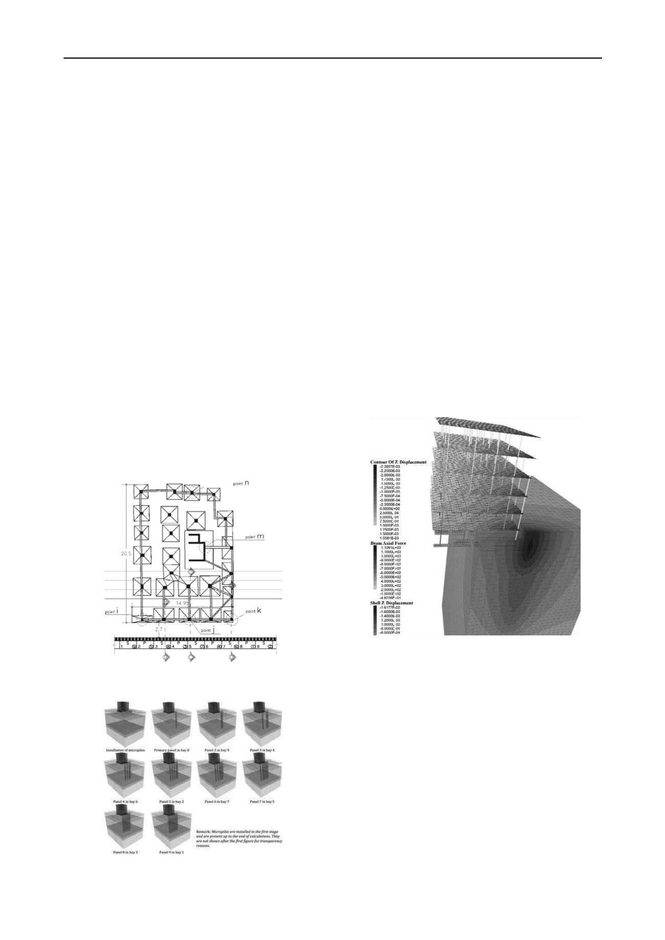
Figure 2. Individual footings of a 6-story building together with the
diaphragm wall and the micropiles
Figure 3. Sequence of panel installation
3 NUMERICAL RESULTS
The contour values for soil settlements, the building floors’
settlements and the axial forces of the building columns
developed after the completion of the first element (element no
8) are illustrated in Figure 4. For visibility reasons the figure is
given in a section at the building face and a cross section at the
middle of the building. It can be seen that the maximum soil
settlement is located around the excavated panel and is of the
order of 2.4 mm. The maximum settlement of the building is
located at its corner nearby the excavated panel and the contours
show a uniform reduction with distance from that point.
The sequential construction of the next panels provokes the
maximum effect in front of each panel, as it has been expected,
but at the same time contributes to a progressive increase of
settlements in a widespread zone. When the primary panels are
installed, an increase of settlements to the value of 4.2 mm is
occurred. The soil settlements progressively decrease with the
distance form the diaphragm wall and are almost zero at the
backside of the building. The completion of the wall with the
rest 4 secondary panels does not encounter significant increase
to the maximum value of the soil settlements. The final value of
maximum settlement is 5.3 mm and the same value is developed
at the external side of the building close to the diaphragm wall.
From the comparison of the axial forces variation throughout
the construction of the panel arises that the panels’ installation
does not practically affect them.
Figure 4. Soil and building settlement contours together with column
axial forces after the completion of the first panel (bay no 8)
Figure 5a illustrates the variation of the horizontal
displacements with depth below the external boundary of a
footing at the front side of the building (cross section ‘C-C’).
The values are not exceeding the order of 1.0 mm and this is
mainly due to the existence of the micropiles. The construction
of the panels with bay no 8 and 9 (first and second in
construction sequence) are relatively too far from that point and
they do not provoke any horizontal displacement at the point
under consideration. The panel with bay no 5 is just in front of
the point and this explains the important movement of the
displacement field during the construction of this panel. Similar
are the results in the case of the point below the footing at the
edge of the external footing at section ‘D-D’, Figure 5b.
The most important effect to the adjacent building is the
anticipated settlements, the angular distortion that will develop
to the foundation and if that last could be capable of provoking
any notable bending moment to the foundation elements. Figure
6 illustrates the progressive increase of the settlements across
the section ‘C-C’. On the same figure the location of the
diaphragm wall and the foundation of the building are shown.


