1952
Proceedings of the 18
th
International Conference on Soil Mechanics and Geotechnical Engineering, Paris 2013
surrounding elements depending on the internal gravitational
stresses, the stiffness and the shear resistance of the surrounding
soil elements, and the arching developed around the trench. This
complicated mechanism provokes a redistribution of stresses
and the surrounding soil elements undergo some deformation.
As a result horizontal displacements at the wall/soil interface
are governed by the ability of the soil to move in response to the
reduction in lateral stresses during the wall installation. The
above mechanism leads to a temporary reduction of the
horizontal stresses in the surrounding excavation faces, which
however increase to the hydrostatic bentonite slurry pressure in
the next stage of excavation. When the excavation of a panel is
accomplished concrete is cast in place using tremie pipes. The
same numerical process is applied to simulate the panel
completion, i.e. appropriate values are attributed to the bulk and
the shear modulus of the material simulating wet concrete,
while, stresses are initialised to the values hydrostatically
defined from the weight of wet concrete. When equilibrium is
attained, regular concrete values are attributed to bulk and the
shear modulus to the panel. The above simulation process is
repeated over the entire depth of the panel.
The aforementioned simulation process reflects the construction
of a single panel and is applied to all panels in a diaphragm
wall. However, the response of each particular panel is greatly
influenced by the construction sequence. Obviously when
constructing a subsequent panel, with already completed
adjacent panels, the effect of arching is strengthened due the
high resistance of these elements. As a result a stress increase is
observed not only at the adjacent soil, but also on neighbouring
panels that have already been casted. Thus over the period of
wall construction there will be a progressive transferring of load
back and forth laterally, either from a primary panel to the
adjacent soil or, as the wall progresses, from new panels to
panels previously casted. It can be realised that when accurate
prediction of displacements and stresses redistribution are
demanded, a profound 3-D nonlinear multi-stage numerical
analysis is required.
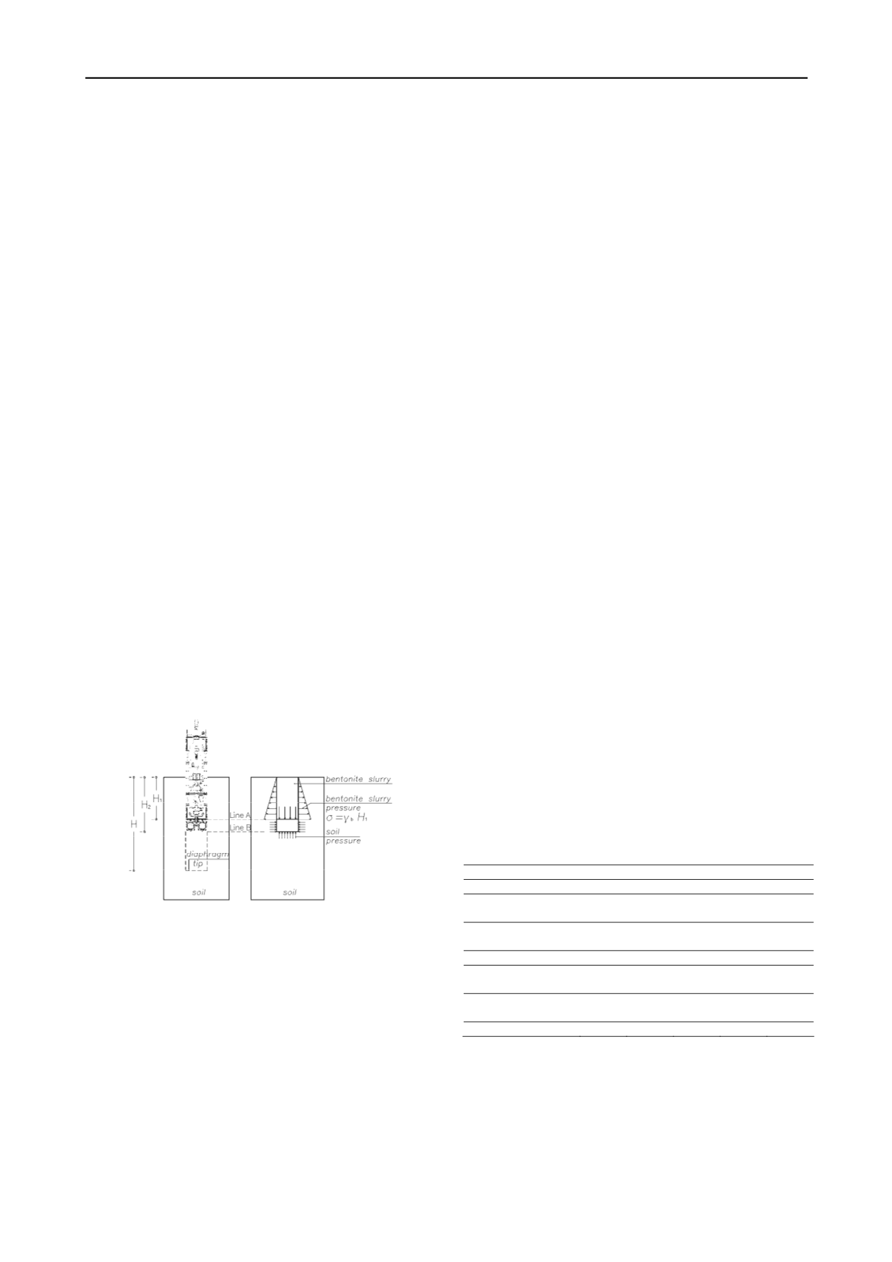
Figure 1. Schematic illustration of the proposed approach for simulating
a single panel excavation
2 NUMERICAL SIMULATION
2.1
Project description
The station of Analipsis, 210 m long and 16.4 m wide, is
considered as one of the most critical of the underground of
Thessaloniki. With the exception of the surficial layer the soil
conditions are relatively good. However, the fact that the
diaphragm wall is located very close to adjacent buildings with
poor foundations, in many cases, renders the construction of the
diaphragm wall extremely demanding. According to the
guidelines of the German code DIN 4126, the critical zone
around the trench excavation extents up to a distance of 70% of
the pile length. For this reason a relatively small typical panel
length
L
= 2.8 m was applied and a rotary cutting machine was
selected to perform the ongoing excavation of the panels. The
thickness of the panels is
t
= 1.20 m, its depth is
H
= 44.0 m and
the basement of the station is 28.0 m below the ground surface.
2.2
Soil model and material properties
The ground conditions at the site together with the soil
properties of each soil layer, derived from the carried out
geotechnical investigation and the evaluation of in-situ and
laboratory tests are presented in Table 1. The groundwater level
was encountered at 5.0 m below the ground level. Pressuremeter
tests were carried out at the area to assess the in situ horizontal
stresses and, according to the evaluation of the results, a
constant value of
K
0
= 0.54 has been adopted.
Bearing in mind the crucial effect and the necessity for
settlements predictions to the adjacent buildings, a constitutive
law with double yielding (FLAC 3D) has been applied in the
present study. The model includes a volumetric yield cap
surface in addition to Mohr-Coulomb shear and tensile failure
envelopes. The cap surface is independent of the shear strength
and it consists of a vertical line on a plot of shear stress vs mean
stress with a trace on the mean stress axis defined as cap
pressure
p
c
. Any violation of the cap surface produces
volumetric plastic strain following a piecewise-linear law
prescribed in a user-supplied table. The tangential bulk and
shear moduli evolve as plastic volumetric strain takes place
according to a special law defined in terms of a constant factor,
R
, which is the ratio of elastic bulk modulus,
K
c
, to plastic bulk
modulus,
K
t
. The relevant values adopted are given in Table 1.
The concrete diaphragm wall behaviour was considered as an
isotropic linear elastic. Linear elastic behaviour was attributed
to the bentonite slurry with infinitesimal deformation values.
The shear strength of bentonite slurry with unit weight of 11
kN/m
3
is of the order 50 Pa (DIN4126). A reasonable value for
the slurry shear modulus is three hundred times the shear
strength,
G
sl
= 15 kPa, while the Poisson’s ratio was taken equal
to 0.49. The application of these values to the analysis produced
stresses within the bentonite computational domain equal to
hydrostatic gravitational state, ensuring that appropriate
hydrostatic pressures were developed at the trench faces. A
higher value of unit weight (12.5 kN/m
3
) has been attributed to
cutting products mixed with bentonite slurry and similarly the
shear modulus has been taken equal to 25 kPa. Taking into
account that the construction schedule, the time period between
adjacent panels installation, particularly the primary panels, is
quite enough for any excess pore dissipation an effective stress
analysis was applied.
Table 1. Geotechnical properties of soil layers.
Layer
Fill
A1a
A1b
A1c
B
Depth (m)
0 – 3
3 - 10 10 – 35 35 – 40 40 -60
Effective cohesion,
c
’
(kPa)
3
3
5
40
50
Effective angle of
friction,
φ
’ (deg)
30
25
25
25
25
Poisson’s ration,
v
0.3
0.3
0.3
0.3
0.3
Plastic bulk modulus,
K
t
(kPa)
4,000
5,000
8,500 10,000 10,000
Ratio of elastic to
plastic bulk modulus,
R
5
6.5
10.5
12
12
Cap pressure,
p
c
(kPa)
100 100 NC* NC* NC*
Remark: NC means that cap pressure is equal to the in-situ mean stress
2.3
Simulation procedure
The effective numerical simulation of typical construction
procedure for a cast in situ diaphragm wall must reflect the
stages and the mechanisms developed during the excavation and
throughout the completion of the wall. The first step was to
establish the in-situ state of stresses. The construction of a
single panel was simulated in 22 stages during which the
excavation was advanced in 2.0 m. Within each stage the soil in


