1942
Proceedings of the 18
th
International Conference on Soil Mechanics and Geotechnical Engineering, Paris 2013
wetting of solid ingredients results from the shearing action
which takes place in the specially designed impellers and
matching casings of the colloidal mixers. The colloidal grout
of specific gravity upto 1.8 to 2 is obtained using these high
velocity mixers. Colloidal grout has enough fluidity to flow
like grout and does not get separated when it comes in contract
with water. It displaces water from the voids of stone/rubbles
due to high specific gravity.
The double drum stonecrete mixer produces colloidal grout
at the rate of 5 to 10 M
3
/hr. of 1:2 mix or 6 to 12 M
3
/hr. of 1:3
mix. When colloidal grout is stored without agitation in tanks
after mixing, a little settlement is to be expected because sand
invariably contains some oversize particles. When it is pumped
direct by the mixer to the work in normal practice, the oversize
particles do not have time to settle out.
4.8 Placement of Colloidal Grout.
Colloidal grout does not mix with water unless agitated with it.
The colloidal grout so prepared is pumped, through 80 mm
Φ pipes placed in the rubbles using special roto or colmono
pumps. The grout will be pumped at the bottom of pre-packed
stones under pressure and will be allowed to rise uniformly in
the cell displacing all the water from the voids due to its
gravity. Once the grout travels upto the top of the course, the
colgrouting is stopped when it emerges out of boulders at a
level of 193.50 m of working platform level. After which the
crawler mounted cranes will be advanced to tackle the next cell
of the coffer dam till entire length 220 m length of u/s coffer
dam is completed from one end. Construction sluices were left
in the u/s coffer dam for diverting the water in final stages of
closure of the coffer dam.
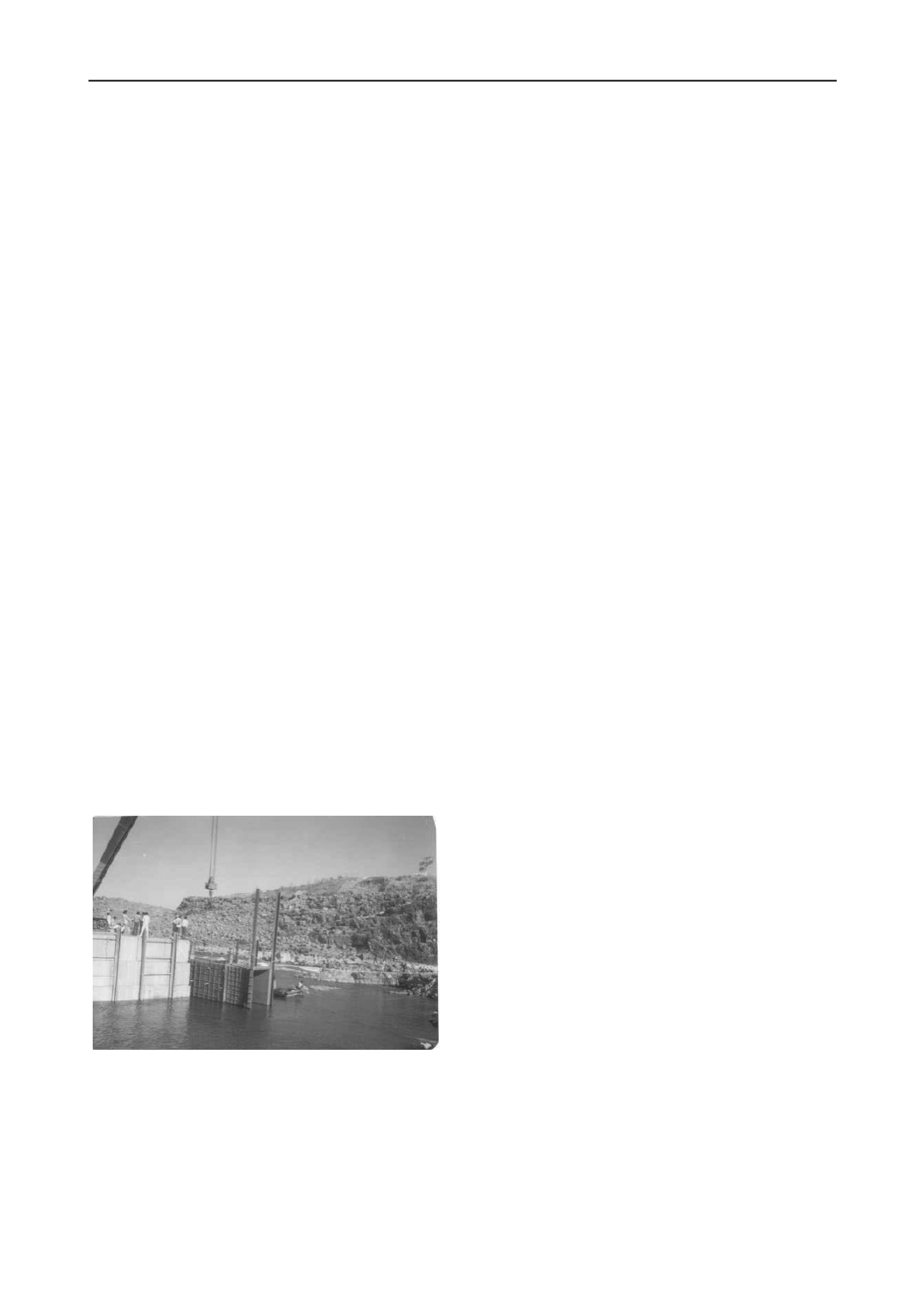
4.9 Construction Sluices.
Pre fabricated M.S. sluice barrel were lowered in the central
portion of u/s coffer dam keeping invert level at RL 186. In all,
six sluices of 2 m x 3 m were installed. Rigid steel boxes were
provided in the blocks for forming the approach tunnel for
sluices. The construction sluices were installed under water
with the help of the expert divers and is shown in photograph
below.
4.10 Masonry Works above water level
.
Construction of masonry in the flank blocks and above water
level on stonecrete platform, upto top of coffer dam was done
using conventional method of construction. The coffer dam
above RL 193.5 was constructed in masonry upto RL 204.5 M
and is shown in photograph. This was taken up immediately
after the construction upto RL 193.5 under water using
stonecrete. A coping 150 mm thick was laid at RL 204.5 m on
the masonry using M-20 grade concrete.
5. DRILLING AND GROUTING.
5.1 Consolidation Grouting.
Looking to the geology, it was recommended to adopt a grid of
drill holes at 3 m c/c on both side, besides about 82 Nos. of
special grout holes were identified keeping in mind the location
of various fault zones.
Depth of consolidation grout holes was 6 m in foundation
rock.
6. CURTAIN GROUTING.
It was recommended to provide a single row of grout curtain, 1
m from the u/s face of the coffer dam, spacing of holes were
kept as 3 m c/c. Depth of grout curtain holes in foundation
rock was kept as 15 m.
This grout curtain was provided in stages of 5 m of drilling
and grouting in descending order method.
It was observed that in consolidation grouting, intake of
cement was 45 kg/meter and in curtain grouting it was 26
kg./meter.
7. D/S. COFFER DAM:
The construction of d/s coffer dam was done using the same
methodology as explain under para 3 sub para I to IX. The top
of d/s coffer dam was kept as 203.50 m i.e. 1 m below the u/s
coffer dam. The main purpose of this coffer dam was, not to
allow the river water which was diverted through the diversion
tunnel (back water) in the d/s of the river.
Closure of Sluices 6 Nos. in coffer dam:
It was essential to ensure following works completed before
closure of sluices were taken in hand :-
8 CONCLUSION
Coffer Dam u/s and d/s, for the Indira Sagar Project had been
successfully constructed and performed well, as a result the
work of 92 m high I.S.P. main dam could be expeditiously
carried out on mighty Narmada River.
The unique and innovative design, using 5 Tons Pre-cast
hollow blocks with underwater stonecrete technique for the
first time in the country, has successfully been used in Indira
Sagar Project.
9 REFERENCES
Ahmed M.J. - Assessment of Geological and Technical inputs
for optimization of Designs of Indira Sagar Project, M.P.
India.
Billore M.S., Geed V.K., - Photographs.
M. Krishnamoorthy, G.C. Vyas, Rajeev Sachedeva
–
Civil
design aspects of Indira Sagar Project.
Tripathi D.C. Amitabh Sharan, - Shearzone treatment : A case
study of Indira Sagar Project on Narmada River, M.P.
India.


