1937
Technical Committee 207 /
Comité technique 207
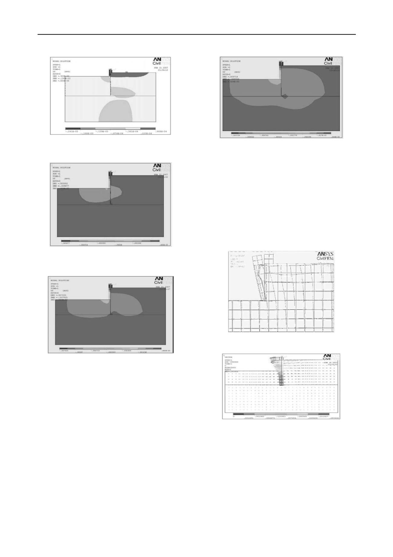
Figure (2-b) Contour of Deflections along the Pile After Excavation to -
2.5 m .
Figure (2-c) Contour of Deflections along the Pile After Excavation
to -5 m .
Figure (2-d) Contour of Deflections along the Pile after applying 210 kN
Horizontal Load .
In figure (2-e), Applying 30 ton horizontal load, It is noted that
increasing the applied lateral load resulted in increasing the
lateral movement of pile towards the excavation, increasing the
wedge of soil in front of the pile (left side) exhibits a bigger
movement mobilizing a passive resistance in the front of the pile
the movement propagates deeper than the previous case, the
surcharge load settlement effect began to finish and a small
passive resistance induced at the pile tip.
Figure (2-e) Contour of Deflections along Pile for 300 kN Horizontal
Load .
figure (3 -a) shows the deformed shape of pile and soil along the
pile at failure, and figure (3 -b) shows the vector plot of the
deflection of pile and soil along the pile at failure,
It is noted that reaching the ultimate lateral load resulted in
increasing the lateral movement of pile towards the excavation,
increasing the passive resistance wedge of soil in front of the
pile (left side), all these resulted in reaching the pile its yielding
and pile rotation increased, consequently, followed by a
progressive slope failure on the right side which is clear in
figures (3 -b).
Figure (3 -a): Deformed and Undeformed Shapes near Ground Surface .
5B
Figure (3 -b) Vector Plot of the Pile and Soil Displacements at Failure.
Considering the lateral displacement UY as the main output,
numerical differentiation process were performed to get the
slope , bending moment, shear force, and the soil reaction
according to equations 1, 2, 3 , and 4 by changing the variable
UX by UY .
Where: UY, MX and PY are deflection, bending moment and
soil reaction (pressure) respectively. Direct generation of soil


