1941
Technical Committee 207 /
Comité technique 207
4 CONSTRUCTION SEQUENCE OF COFFER DAM U/S.
Following is the Construction sequence.
4.1 Casting yard for Pre-cast hollow blocks.
A casting yard having all facilities to cast hollow blocks under
controlled conditions was made on left bank.
The pre-
cast/hollow blocks of size of 1.5 m x 1.5 m x 1.5 were casted in
this yard. Suitable storage for form work and construction
materials like stone grit, sand, water curing tank etc. were
arranged on this platform to keep adequate stocks at site. The
yard was equipped with form vibrators etc. and the traveling
gentry with 10 T capacity. One electric hoist was fitted at this
platform. The blocks were handled and loaded in flat bottom
trucks by said gantry to carry it upto working platform on left
flank from where, finally they were taken for construction
using crawler mounted cranes at site.
4.2 Precast Hollow Blocks :-
It was proposed to use hollow-precast blocks in the u/s and d/s
of the dam profile under water. This enclosure were termed as
stonecrete cell. At a time, 15 m length of coffer dam was
undertaken in hand. Selected rubbles were filled within this
enclosure along with colgrout pipes to carry out under water
work. These colgrout pipe of 80 mm ø were kept in a grid of 3
m and individual pipes were surrounded with a circular coil
made of 6 mm, Tor to protect them during boulder filling.
These blocks in addition to forming the enclosure have helped
to stop flow of water within the enclosure as well as in voids of
the rubbles.
The shape of the blocks on upstream and down streams
faces of the coffer dam were nearly confirming to the designed
profile.
To provide necessary interlocking amongst the blocks,
male and female grooves were provided in each block. The
blocks of special dimensions for maintaining uniform level of
courses were casted as per requirement. The necessary shear
keys and lifting hooks were provided in each block. The
blocks were casted in the rigid steel forms so as to ensure
uniform dimensions and minimum tolerances. The blocks were
cast in advance and stacked in the casting yard.
4.3 Preparation of Foundation.-
The left and right flanks which were much above water level of
river were excavated to reach sound rock level to accommodate
the length of coffer dam. Right flank in particular, was braided
with clayey gaougey shear seam of varying thickness from 2m
to 6m. On the left flank excavation bedding shears of 16 to 25
cm thickness confined to the silt stones were commonly seen.
Few photographs of the excavation and shear seam are
exhibited below.
Foundation preparation in the river portion comprised of
removal of silt, debris, loose rock and leveling of bed rock by
underwater blasting wherever necessary. This was done using
expert divers.
In order that the precast blocks from the pattern masonry
walls required to be raised in uniform courses, the precise
soundings were taken and loose materials were removed from
its underneath. The area was leveled using special sizes of the
blocks, or executing under water concreting for leveling course.
It was observed that foundation rock was undulated at places.
Hence levels were taken at a grid of 2 m and drawn on graph
sheet. The gap between the leveled foundation and underneath
of the blocks were caulked to achieve reasonable water tight
joint.
4.4 Launching of Blocks.
After the river bed is cleared of loose materials and leveled to
receive the first course of the blocks as described under
preparation of foundation para (III) above, the pre-cast hollow
blocks were lifted from the working platform and carried by
crane and lowered in position in the cell. Before lowering the
PCC blocks, a steel frame made of 100 mm M.S. angle, is first
lowered in place on 40 mm bed of stone chips and this frame is
leveled horizontally on this bed. Expert divers had positioned
the blocks at proper places either on the u/s or d/s of the
enclosure as required, but within these steel frames which were
leveled horizontally on the bed of 40 mm stone chips.
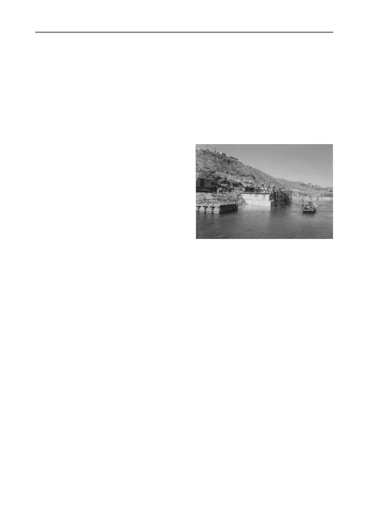
Each operation of block launching consisted of placement of
blocks in the bottom course, to be followed by blocks in upper
course. Till they were placed upto the level of 193.50 M. The
launching of blocks is shown in photograph above.
Normally the blocks will be placed in required courses
on up-stream and downstream sides of the u/s and d/s coffer
dams. As the blocks are required to be in course it will be
imperative to break the joints between the courses. Proper care
was taken to break these joints in subsequent courses. As a
matter of abundant precaution, the space in between the rows of
blocks, will be filled with selected rubble near the blocks and
around the pipes placed for colgrouting, so that the same does
not get disturbed while filling up of rubble/stones in the cell
4.5 Packing of Rubbles
.
After the blocks are carefully launched and erected on either
side in courses and the space in between intersped with colcrete
pipes, as stated above, rubble will be placed to fill-up the entire
space between the rows of blocks in a 15 m cell. This rubble
filling shall be done layer by layer in a systematic way using
the large buckets with drop bottoms, handled by cranes.
4.6 Stonecreting Operations.
The stonecrete process consists of making a grout of cement,
sand and water in which cement has been so completely
hydrated by high speed mechanical mixing, that the grout
attains a colloidal form. This grout is stable and particularly
fluent.
It contains no chemical admixtures which might
ultimately be harmful.
When colloidal grout is poured in
rubble aggregate the voids in the rubble filling are completely
filled by penetration and the whole mass sets as a dense, solid
concrete which is termed as
“STONECRETE”.
4.7 Preparation of Colloidal Grout
.
The Colloidal grout was prepared in double drum colcrete
mixer consisting of sand, cement and water in desired
proportions to obtain colloidal grout. In colloidal mixer, the


