1929
Technical Committee 207 /
Comité technique 207
Figure 5. Examples of the enormous inhomogeneity of the local soils and
rocks.
“Internal”, “external” and “compound” stability modes were sepa-
rately checked to keep conformity with the preliminary designs in
2004, although this differentiation is questionable; for more details see
Alexiew (2004 & 2005).
Note that in the meantime in the new issue of the German recom-
mendations EBGEO (2010) the distinction internal-external-
compound was eliminated, as well as e.g. the formal distinction be-
tween “slopes” and “walls”.
Geogrids from the “FORTRAC® T”-family were chosen as rein-
forcement due to their high specific short- and long-term strength, low
short- and long-term strain, low creep, high coefficient of bond to a
wide range of soils and flexibility resulting into an easy installation.
The range of geogrids for this project was from FORTRAC® T 55 to
FORTRAC® T 200.
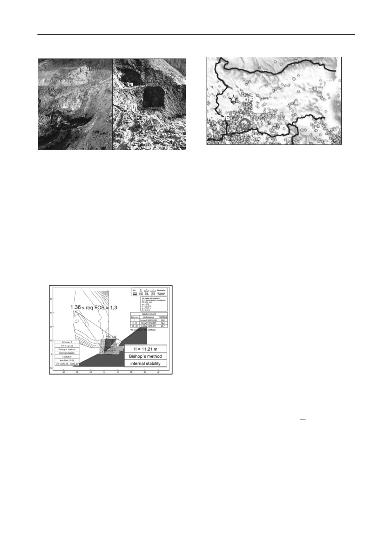
The required factors of safety (FOS) were chosen according to the
Bulgarian Standards with FOS > 1.3 for normal (static) conditions. In
Figure 6 a typical Bishop circle analysis is shown (for the internal sta-
bility only, say the failure surface crosses exclusively the reinforced
zone).
Figure 6. Typical example of stability analysis according to Bishop (only
“internal” shown)
.
A specific issue was the seismic analysis; the region is of signifi-
cant seismic activity with a magnitude of VII acc. to Richter.
The Bulgarian concepts for seismic design from 1980 being still
valid with small modifications during the period of analysis were
adopted throughout the project (CDBSSR 1987, CDRW 1986,
SGDSR 1987).
Figure 7 shows an overview of the seismic activity in Bulgaria to-
gether with the position of the Devin-Mihalkovo project and the zone
with VII acc. to Richter with a coefficient of horizontal acceleration k
h
= 0.15. A vertical acceleration is not being taken into account.
For the acting seismic forces F
seismic
the Equation 1 can be used
(CDBSSR 1987, CDRW 1986, SGDSR 1987):
Figure 7. Seismic activities in Bulgaria, the project position is marked.
F
seismic
= 1.30 . R
response
. k
h
. (permanent loads +
+ 0.50 . traffic loads)
(1)
where R
response
= coefficient of response of the structure to seismic im-
pact; k
h
= coefficient of horizontal acceleration; 1.30 and 0.50 = par-
tial safety factors on the side of action for seismic design cases.
R
response
has higher values e.g. up to 0.40 for rigid
(brittle, e.g. ma-
sonry, concrete) structures and lower values e.g. 0.25 for ductile struc-
tures like earth dams and embankments. It seems logic and conclusive
that earth systems reinforced by flexible geogrids should be at least so
ductile and able to dissipate seismic energy remaining intact as non-
reinforced earth dams.
This concept and the corresponding calculation results seem to be
coherent with the experience, conclusions and recommendations in
e.g. Tatsuoka et al (1998) and other publications confirming the very
advantageous behavior of GRS-walls under seismic impact.
Note that for seismic analyses the Bulgarian codes (CDBSSR
1987, CDRW 1986, SGDSR 1987) ask for a FOS > 1.1, for more de-
tails and previous “seismic” projects see e.g. Jossifowa & Alexiew
(2002).
One specific issue more in the Bulgarian codes is the reduction of
the angle of internal friction acc. to Equations 2 & 3 depending on the
intensity of earthquake:
φ
characteristic, seismic
= φ
characteristic, static
- Δφ
(2)
where
Δφ = Δφ
(magnitude acc. to Richter) (3)
For the project under discussion with a magnitude of VII acc. to
Richter Δφ = 3.5°.
Because the software used (GGU Stability by Civil Serve) does
not include a calculation conform to Equation 1 and considers only di-
rectly k
h
, the latter had to be modified “by hand” before the input.
5. EXECUTION, PROBLEMS, SOLUTIONS, EXPERIENCE
Execution started in summer 2007. First problems arose soon: the to-
pography deviated sometimes significantly from the expected one, the
real terrain was sometimes higher or lower than it should be, the real
slope inclination often steeper. Step by step many of the cross-sections
had to be re-designed. At the end of the day all GRS-walls, even the
highest with over 20 m height, became “bermless”, what is quite
unique.
The “bermless” solution offers significant advantages: the base width
of the cross-sections becomes minimal (Figure 3). This helped to
avoid deep cuts into the hillside and/or an expansion of the trapezoid
beyond the steep slope line (to the left in Figure 3). Additionally, in
some cases the geology deviated significantly from the assumptions;
this resulted in re-design as well.
Often surprising water veins in the natural slopes had to be
drained promptly. For this purpose thick wicks from rolled non-woven
geotextiles were installed ending on the front side of wall as a quick
ad hoc solution.
In Figure 8 typical construction stages and details are depicted.
Figure 9 shows one of the completed walls just before handing the
route over for operation.


