1924
Proceedings of the 18
th
International Conference on Soil Mechanics and Geotechnical Engineering, Paris 2013
reinforced fill and had to be cut and anchored in order to widen
the roadway.
Therefore, this layer was fully investigated with:
Several SPT borings.
Laboratory tests: direct shear and expansion tests on
undisturbed samples and characterization.
Pullout tests on anchors.
Moreover, compaction and direct shear tests were carried out on
fill materials.
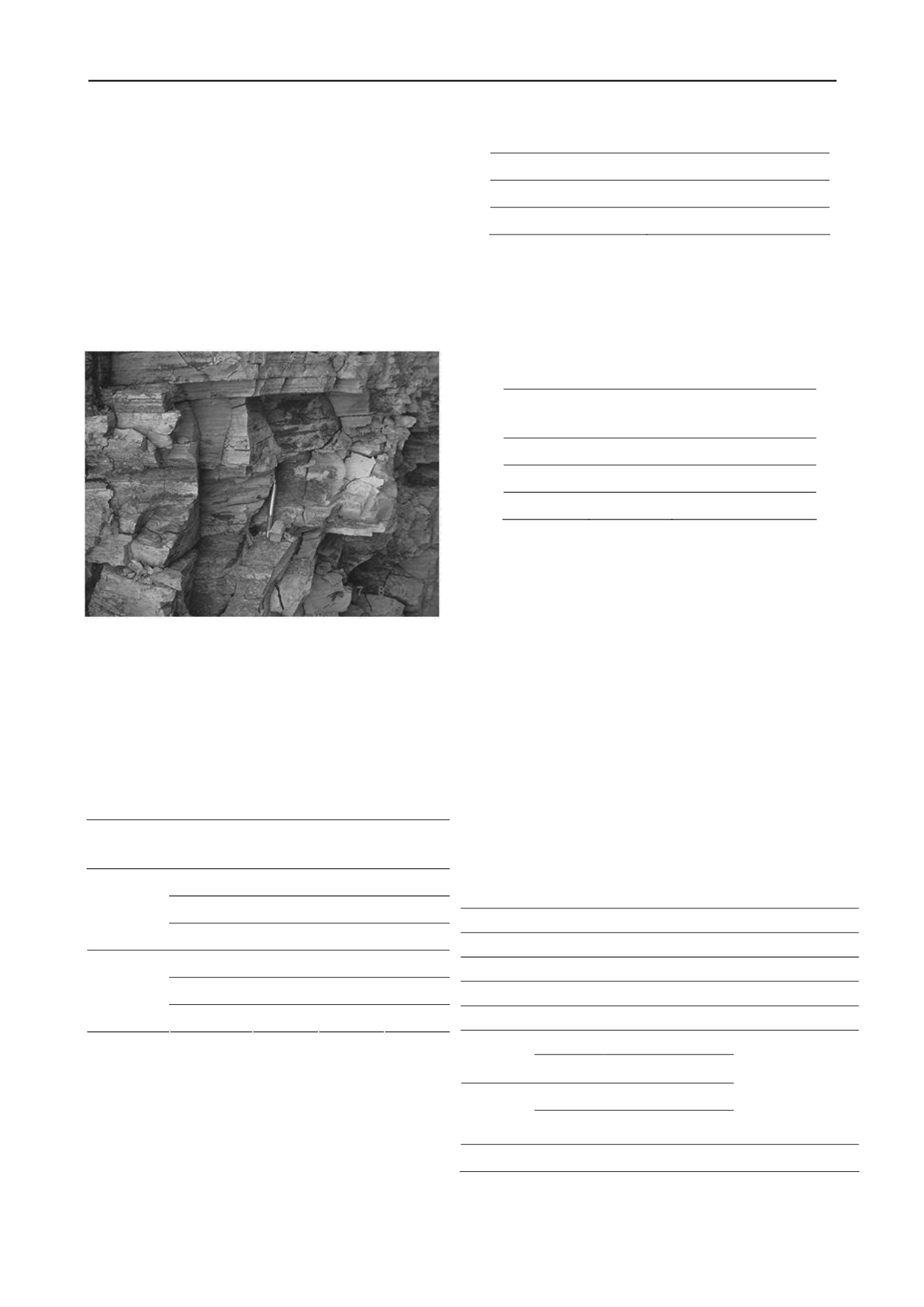
Figure 2. Stiff to hard silty clay layer to be cut and retained with
anchored wall and surcharged with reinforced soil fill.
3 TEST RESULTS – STIFF TO HARD CLAY
Table 1 presents results from direct shear tests. It is worth
noting the large drop in shear strength for large displacements
(residual conditions). Peak strength typically occurs for very
small displacements, in the range of 1mm.
Table 1. Direct shear test results.
Sample
Specimen
(kPa)
máx
(kPa)
res
(kPa)
CP-1
51
232
32
CP-2
154
305
22
Natural
CP-3
306
419
92
CP-1
51
228
77
CP-2
151
264
72
Saturated
CP-3
304
304
34
Table 2 presents results from expansion tests carried out on the
horizontal and vertical directions. The expansion pressure is
very high in the vertical direction, whereas the expansion
pressure in the horizontal direction is around 6% of the vertical
pressure, showing the marked influence of clay structure on its
behavior (Figure 2).
Table 2. Expansion pressure for vertical and horizontal directions.
Direction
Expansion Pressure (kPa)
Vertical
440
Horizontal
30
Table 3 presents results from pullout tests on anchors 10cm in
diameter and 6m long as a function of injection pressure.
Anchors 202, 207 and 212 had, respectively, one, three and two
functioning pressure valves. Therefore, adhesion values varied
significantly from 25 to 45kN/m, demonstrating marked
influence of injection pressure on adhesion.
Table 3. Pullout tests on anchors.
Segment
Adhesion
(kN/m)
Injection Pressure
(kgf/cm²)
202
25
(1 valve)
207
45
50/20/30 (3 valves)
212
30
(2 valves)
4 DESIGN PARAMETERS
The following design conditions and strenght parameters were
considered for design:
End-of-Construction (EOC): peak shear strength parameters
and natural water content, with and without expansion
pressure.
Long-Therm and Peak Condition (LTP): saturated peak shear
strength parameters, with and without expansion pressure.
Long-Therm and Residual Condition (LTR): saturated
residual shear strength parameters, with expansion pressure.
A possible decrease in adhesion due to soil saturation was also
considered in adhesion. Increase in anchor loads due to
expansion pressure was taken into account for anchor design.
With basis on the laboratory and field tests, and following
the procedures outlined in ABNT NBR 11.682 – Slope
Stability, the parameters presented in Table 5 were used in wall
design.
Table 5 – Design parameters.
Condition/
Parameter
EOC
LTP
LTR MSE*
Soil unit weight (kN/m³)
20
20
20
20
Cohesion intercept (kPa)
60
40
0
30
Friction angle (º)
30
18
18
25
Average
100
90
Anchor
adhesion
(kPa)
Maximum
140
125
Average
70
65
Same with
expansion
(kPa)
Maximum
100
90
125
Puncture anchor head (kN)
430
-
*MSE :Soil Parameters for Mechanically Estabilized Earth Wall


