1920
Proceedings of the 18
th
International Conference on Soil Mechanics and Geotechnical Engineering, Paris 2013
Ö. Bilgin and E. Mansour
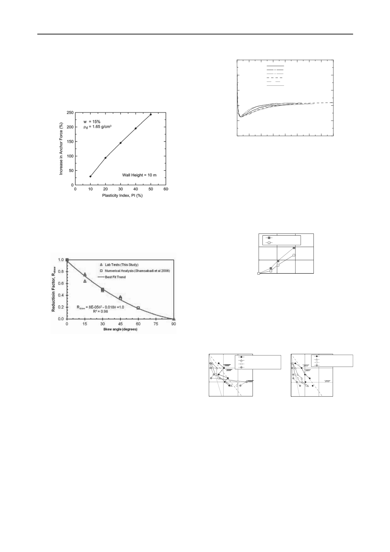
discuss theoretical analysis of
sheet piles in expansive soils. The presented analyses are based
on a correlation between the plasticity index (PI) and swelling
potential. The analyses presented assume that swelling pressure
will act in the zone where moisture varies, relatively close to the
surface. Figure 8 presents results of the authors analyses,
correlating anchor loads of sheet pile wall to the PI
Figure 8. Effect of expansive soils on anchor force, according to
Ö.
Bilgin and E. Mansour
S. Jessee and K. Rollins
present model tests to evaluate
passive earth pressure on a “skewed” surface. Figure 9 presents
a proposed reduction factor for the passive force, as a function
of the skew angle.
Figure 9. Test results presented by
S. Jessee and K. Rollins
.
The performed tests showed that a significant reduction was
obtained as the skew angle increases. These results were
compatible with numerical simulations and a simple correction
factor is proposed. Peak passive pressure was developed at
2,5% to 3,5% of abutment height. Significant reductions in
passive pressure were measured beyond peak (4% to 6%), with
a residual stress around 40%.
Results are interesting, but direct use of results for design
shall be evaluated with care.
D. Loukidis and R. Salgado
present the results of
sophisticated numerical simulations of variation of earth
pressure on walls supporting granular soils. Figure 10 present
one of the presented outputs and some interesting qualitative
conclusions can be drawn:
For horizontal displacements of around 0,5%, minimum
lateral earth pressure develops. Considering K
0
around 0,5, K
a
results around 0,125. As horizontal displacement increases, K
a
results in the order of 0,2. The authors state that the minimum
earth pressure coefficient should not be used, at least for
ultimate limit state design. However, when analyzing figure 7,
where a significant number of case histories showed horizontal
displacements of less than 0,4 %, possibly some optimization
in terms of design earth pressures can be possible.
0.00 0.01 0.02 0.03 0.04 0.05 0.06 0.07 0.08
u
C
/H
0.0
0.2
0.4
0.6
0.8
1.0
K/K
0
H=7m, B=1.5m, D=0.5m
H=7m, B=2.0m, D=0.5m
H=7m, B=2.5m, D=0.5m
H=8m, B=1.5m, D=0.5m
H=6m, B=1.5m, D=0.5m
H=7m, B=1.5m, D=0.2m
Figure 10. Results presented by
D. Loukidis and R. Salgado
: Variation
of normalized lateral earth pressure coefficient with wall crest
displacement from analyses with medium dense Toyoura sand
(
D
R
=60%)
T. Maeda et al.
discuss the use of inclined braceless retaining
structures in sandy soil. The presented evaluations showed that
significant reduction in earth pressures acting on a cantilever
wall can be obtained by inclining the wall facing. Figure 11
present horizontal displacements measured on model tests. It
can be seen that, even for a reduced inclination of 10
o
,
horizontal displacements reduced around 30%.
0
10
20
30
0
5
10
15
Horizontal displacement at top
retaining wall
Excavation depth (m)
Vertical
10deg.inclination
Figure 11. Relationship between excavation depth and horizontal
displacement of retaining walls, considering horizontal and inclined
structures, presented by
T. Maeda et al.
Figure 12 presents earth pressures for the inclined and the
vertical structure. It can be seen that, especially for deeper
excavations, a significant reduction in earth pressures occurs.
0
5
10
15
0
50
100
150
Earth pressure
Beforeexcavation
Excavationof 3.3m depth
Excavationof 5.3m depth
Excavationof 9.6m depth
Earthpressure at rest (0.5)
Coulom'searthpressure
(kN/m
2
)
0
5
0
5
0
50
100
150
Earthpressure
Beforeexcavation
Excavationof 3.3mdepth
Excavationof 5.3mdepth
Excavationof 9.6mdepth
Coulom'searthpressure
Earthpressure at rest (0.5)
(kN/m
2
)
Figure 12. Earth pressures for vertical and inclined structure, presented
by
T. Maeda et al.
In the author´s opinion, the simple approach of inclining
slightly a cantilever structure can bring significant saving,
should be further investigated and can be used in practice.
5.3 Soil nailing and anchor lateral resistance
C. M. Chow and Y.C. Tan
. present data related to the
performance of soil nails in weathered granite and fill. Several
soil nail pull out tests were performed in excavations of up to 20
m depth. Figure 13 presents typical pull out results, showing
that maximum load is obtained between 4 and 6 mm of
displacement. After a peak value, only slight increases can be
seen.


