1925
Technical Committee 207 /
Comité technique 207
5 DESIGN AND CONSTRUCTION OF ANCHORED
WALL
6 WALL MONITORING
A limit equilibrium program was used to design the
anchored wall, considering the reinforced wall on the top and a
traffic surcharge of 25kPa. Potential failure surfaces were
always very close to the anchored wall face. As a result, the free
section of the anchors were short, in the order of 3.0m. This is
the minimum length accepted by ABNT NBR 5629 – Anchored
Walls. Anchor length was varied in order to achieve minimum
Safety Factor of 1.8 for EOC, 1.5 for LTP, and 1.2 for LTR
conditions, resulting the following anchor distribution:
In order to monitor wall behavior a monitoring system was
installed along the wall. It consisted of:
3 inclinometers 15m deep installed
3 load cells installed at selected anchor heads
20 displacement pins
Inclinometers were installed in boreholes along the front face of
the anchored wall, and extended upwards during placement of
the reinforced fill.
Several readings were obtained during construction of the lower
anchored section and continued durgin construction of the upper
reinforced fill section.
Cable anchors, 5x12,7mm 190RB, yield stress= 1708MPa
Working load = 430kN
Testing load = 760kN
Minimum spacing = 1,6m
7 MONITORING RESULTS
Maximum spacing = 2,0m
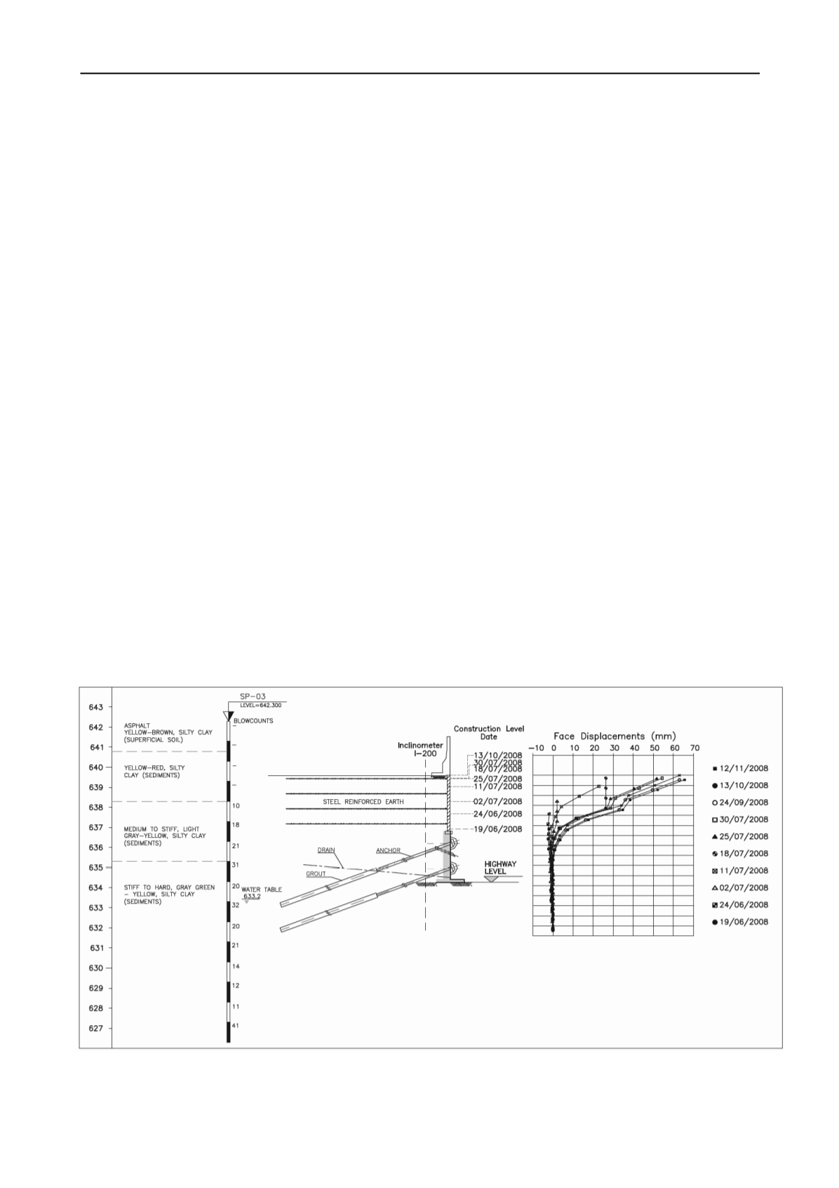
Figures 3 and 4 show inclinometers results for 2 of the
instrumented sections: Section I-200 and Section I-205. The
results show that:
Inclination with horizontal = 20 degrees
Free length = 3,0m
Anchored length = varying from 6.0 to 9.0m
Anchor diameter = 100mm
Water table close to the base of the anchored wall was found
in several SPT bores. Therefore, horizontal drains 15m long
were installed every 2.4m along the wall base.
The displacements increase continuously with construction of
the lower anchored wall and the upper reinforced soil wall.
Displacements of the lower anchored wall were generally
small, in the range of 5 to 10mm.
The stiff clay layer was carefully excavated to install the
anchors and build the reinforced concrete face 30cm thick. For
each anchor level the anchors were loaded to 50% of the
working load. Construction of the reinforcef fill started after the
completion of the anchored wall. When the reinforced fill height
reachedd around 70% of the final fill height the anchors were
re-loaded with 100% of the final working load.
Small face displacementes were expected for the stiff clay
layer. However, for these displacements level it is possible
that residual conditions may be attained by the clay layer
during wall construction.
For the upper reinforced fill, however, face displacements
were relatively high. Measured displacements varied from
around 10mm at the bottom up to 70 to 80mm for the upper
part of the fill.
Figure 3. Inclinometer results in Section I-200.


