1954
Proceedings of the 18
th
International Conference on Soil Mechanics and Geotechnical Engineering, Paris 2013
The construction of every panel contributes to a progressive
increase of settlements, with the maximum influence
experienced when the primary panel close to the cross section is
installed. This explains the maximum difference observed when
panel no 4 is installed. The maximum settlement is developed at
the end of the construction of all panels, its value is of the order
of 5.5 mm and occurs at the front side of the building.
(a) (b)
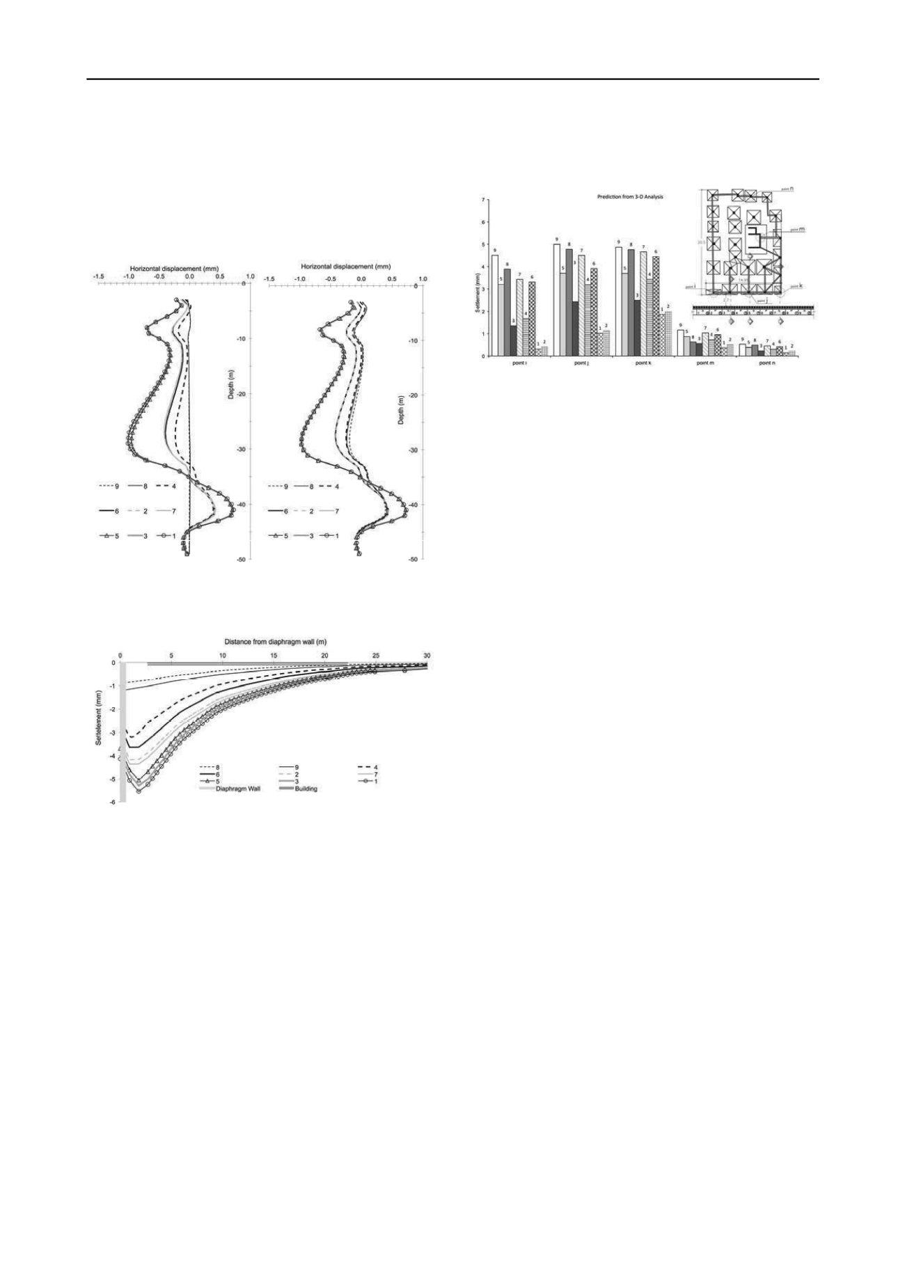
Figure 5. Profile of horizontal displacements below the external footing
at (a) the mid-face, point j, and (b) the end-face of the building, point k
Figure 6. Development of settlement profile with panel sequence
construction at cross section ‘C-C’
It is worth noticing that the settlement values estimated from the
3-D analysis are leading to an angular distortion of 1:5,000.
This value is considerably lower than the limits provided by
CIRIA and the CFEM.
An effective design of complex retaining structures, with
closely adjacent buildings, includes instrumentation and
monitoring to ensure the safety of the construction and control
the effect on the adjacent buildings. These data will be available
when the diaphragm wall at this area will commence and
histograms giving the contribution to cumulative settlements of
each particular panel can be drawn. It is therefore extremely
helpful to give these histograms resulting from the 3-D analysis
and follow up the values as the wall is constructed. Figure 7
illustrates the numerically established cumulative settlements
after the completion of each panel, at the characteristic points, i,
j, k, m and n. The location of each panel corresponds to relative
position from left to right ,while the installation sequence is
given on the top of the histograms.
It can be seen that the final settlements at the front face of the
building (points i, j and k) are of the same magnitude and that
the values provided for the points far from the diaphragm wall
(points m and n) are drastically lower and with no practical
effect on the building. It is clearly evident that Figure 7 can be
efficiently used to compare settlements during the up coming
construction and provide alarm signal in case of significantly
higher settlements values.
Figure 7. Predicted development of cumulative settlements at points i, j,
k, m and n at the end of each panel construction
4 CONCLUSION
In this paper the effects from the installation of diaphragm walls
have been investigated using a new approach for simulating the
excavation and construction of subsequent panels. The method
has been combined with a 3-D nonlinear analysis and a
constitutive law providing bulk and shear modulus variation,
depending on the stress path (loading, unloading, reloading). It
has been observed that the most significant effect in front of a
given panel occurs during the installation of that panel and that
the effect on stress reduction and lateral movements in front of
the subsequent panels is rather limited. The method has been
used to estimate the effects on an adjacent 6-storey building by
applying a full soil-structure interaction including the whole
building. Progressively increased with subsequent panels
installation settlement profiles are given along the building
foundation. Moreover, settlements at specific points where
leveling captures have been installed are given in cumulative
form. The predictions indicate that the angular distortion of the
building remains under the required limits of serviceability and
at the same time provide the guidelines for the monitoring of the
upcoming construction of the diaphragm wall in front of the
building.
5 REFERENCES
Burland J.B. and Hancock R.J.R. 1977. Underground car park at the
House of Commons, London: geo- technical aspects.
Struct Engr
55 (2), 87-100.
Tedd P., Chard B.M., Charles J.A. and Symons IF. 1984. Behaviour of a
propped embedded retaining wall in stiff clay at Bell Common
Tunnel.
Géotechnique
34 (4), 513-32.
Symons I.F. and Carder D.R. 1993. Stress changes in stiff clay caused
by the installation of embedded retaining walls.
Retaining
structures
. Thomas Telford, London.
Powrie W. and Kantartzi C. 1996. Ground response during diaphragm
wall installation in clay: centrifuge model tests.
Géotechnique
46
(4), 725-39.
DIN 4126. 1986.
Cast-in-situ concrete diaphragm walls
. Berlin.
Itasca. 2009. FLAC3D,
Fast Lagrangian analysis of continua
, version
4.0: User’s and theory manuals. Itasca Consulting Group, Inc.
Minneapolis.
CIRIA. 1983.
Settlement of structures on clay soils. Report 113
,
London.
Canadian Geotechnical Society. 1992.
Canadian foundation
engineering manual
. British Publishers Ktd, Vancouver.


