1970
Proceedings of the 18
th
International Conference on Soil Mechanics and Geotechnical Engineering, Paris 2013
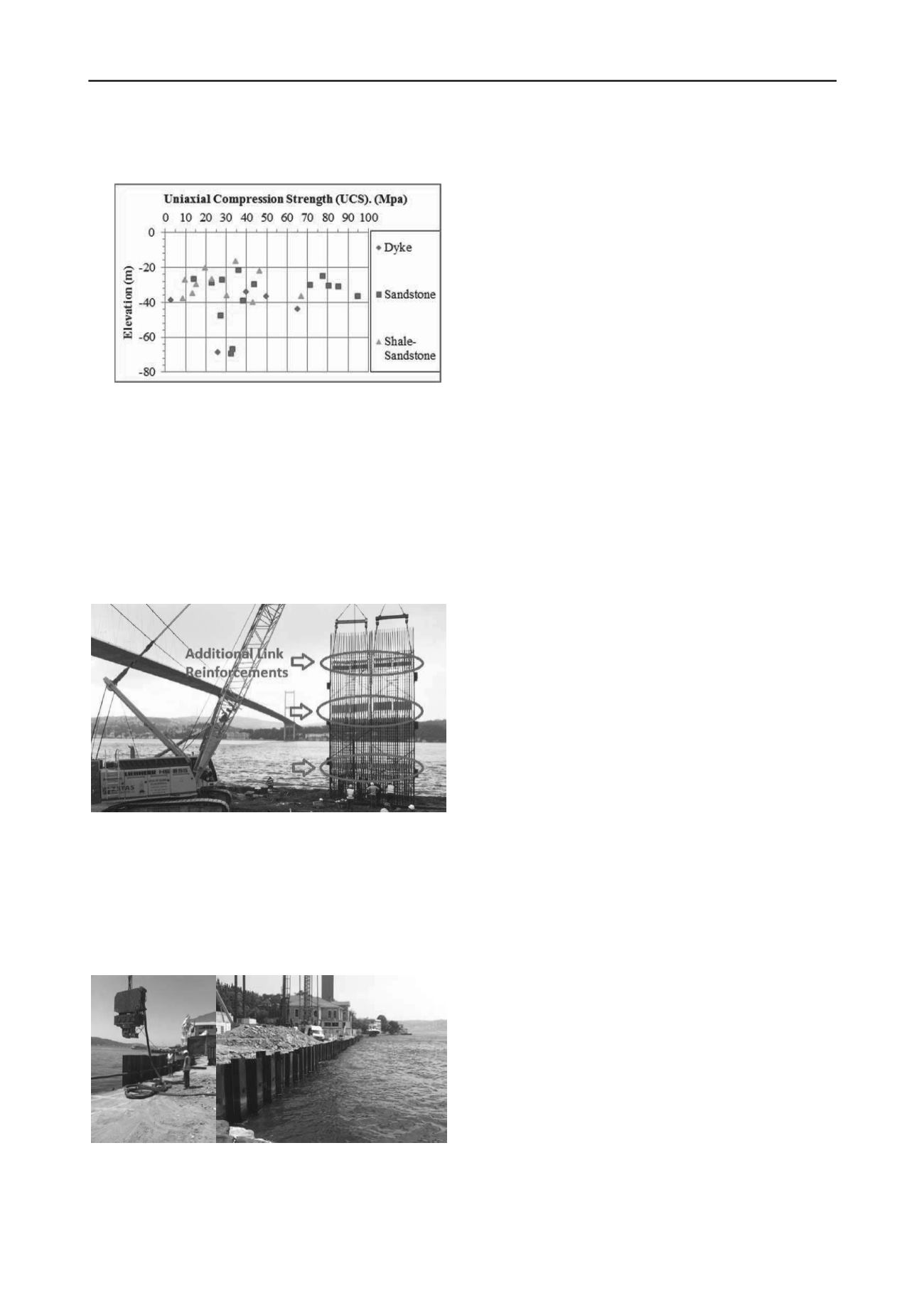
The distribution of the UCS values with the depth is given
in Figure 10.
7 CONCLUSIONS
Figure 10. Unconfined Compression Strength (UCS) Values with Depth
The socket length of the diaphragm wall is variable due to
the variability of the lithology of bedrock. It is estimated that
the minimum 5.0 m socket length in the rock formation will be
required. With the utilized hydrofraise cutter diaphragm wall
machine, it was possible to construct approximately 2.65 m/day
on plan (equals to 60 m² diaphragm wall per day) in average.
To integrate the slabs and foundation with the diaphragm
walls additional link reinforcements are placed in the
reinforcement cage (Figure 11). It is planned to chip the
concrete on these elevations to bend the additional
reinforcement into the slab and foundation elements.
Within the restoration campaign of two beautiful historical
mansions from Ottomans alongside the Bosphorus namely
Hatice Sultan and Fehime Sultan, four basement floors was
planned to be constructed with a maximum excavation depth of
24 m. Tender design for the retaining system of this excavation
was temporary diaphragm walls supported with steel tubular
struts. Due to the lack of enough spacing between the struts,
applicability of the excavation works to achieve the desired
speed was found to be questionable. Therefore an alternative
system of top down construction method was proposed during
the bidding stage. Prior to the excavation, it is proposed to
construct the diaphragm wall and bored piles which will be also
part of permanent structure of the basement so a remarkable
saving and speed together with additional safety could be
provided to the project. Another benefit of this system was also
allowing extension of bored piles which are also columns of the
basement into the bedrock to have desired tension resistance
against uplift. This design gave a chance to eliminate the gravel
pool proposed in preliminary design and provided additional
space in basement floors. Integration of diaphragm wall, slabs
and foundation is realized with additional link reinforcements
and these reinforcements are placed in their for seen locations
during the cage preparation. Sheet piles implemented also
successfully prior to the seaside diaphragm wall construction in
order to eliminate the negative effect of sea. In spite of the high
UCS values it was possible to construct the diaphragm walls
socketing 5.0 m deep into the bedrock with high capacity
hydrofraise – cutter diaphragm wall machine at a reasonable
rate. It is concluded that with the implication of top down
construction method, part of this challenging project is
completed successfully in economical, safe and timely manner.
8 ACKNOWLEDGMENT
We would like to extend our great appreciation to Mr.
Hamdi Topcu, Chairman of Executive committee of Turkish
Airlines and Mr. Atilla Dogudan, Chairman of Do-Co
Corporation. The coordination and cooperation of Guryapi
Construction Company are also gratefully acknowledged.
Figure 11. Additional Link Reinforcements on the Slab Elevations
Prior to diaphragm wall construction on the seaside, it was
planned to implement sheet piles at the shore to remove the
large quay stones at the back side and to prevent the negative
fluctuation effect of the sea during the diaphragm wall
construction. Sheet piles also contribute to the overall stability
of the quay under the weight of heavy diaphragm wall machine.
Sheet piling application is presented in the Figures 12a and 12b.
Figures 12a and 12b Sheet Piling


