1980
Proceedings of the 18
th
International Conference on Soil Mechanics and Geotechnical Engineering, Paris 2013
Proceedings of the 18
th
International Conference on Soil Mechanics and Geotechnical Engineering, Paris 2013
strengths. Retaining walls can be reinforced with concrete or
geogrid made of geosynthetics.
The functional unit is defined as the construction and
disposal of 1 m slope retention with a 3 meters high wall,
referring to a standard cross-section. Thus, the functional unit
is independent of the length of the wall.
Polyethylene and PET granules are used as basic material of
the geogrid. The geogrid has to achieve a long-term strength
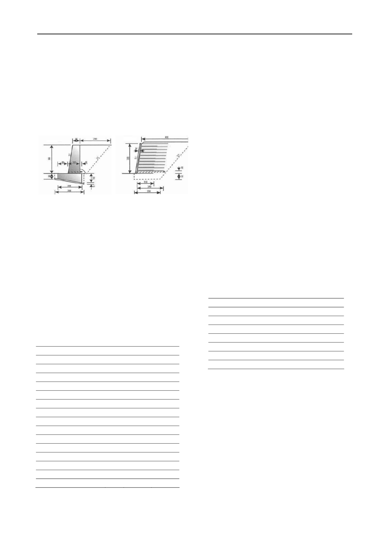
of 14 kN/m. A scheme of both types of retaining walls are
shown in Fig. 1.
Figure 1. Scheme of the concrete reinforced retaining wall (CRRW,
left) and the geosynthetics reinforced retaining wall (GRRW, right)
Some important key figures of the construction of a
reinforced retaining wall are summarized in Tab. 1. The
information refers to one meter of slope retention infra-
structure and a time period of 100 years. Diesel is used in
building machines for the excavation of the foundation and
the compaction of the ground. The NMVOC emissions shown
are released from the bitumen used to seal the concrete wall.
The use of recycled gravel is not considered, since usually no
onsite recycled gravel with specific properties is available
when building reinforced retaining wall for the first time.
Tab. 1 shows specific values of the retaining walls for
both alternatives. The material on site is used as fill material,
wall embankments and cover material in case of a GRRW. A
drainage layer made of gravel with a thickness of at least 30
cm behind the concrete lining is necessary. To be consistent
with the CRRW, a gravel layer thickness of 80 cm is assumed
in both cases. Round gravel is used for drainage purposes .
Table 1. Selected key figures describing the two constructions of one
eter reinforced retaining wall
m
Unit
CRRW
GRRW
Concrete
m
3
/m
1.60
-
Lean mix concrete
m
3
/m
0.24
-
Structural concrete
m
3
/m
2.10
0.31
Reinforcing steel
kg/m
153
-
Gravel
t/m
4.3
4.3
Bitumen
kg/m
2.84
-
Three layered laminated board m
3
/m
0.01
-
Geosynthetic
m
2
/m
-
39.2
Polystyrene foam slab
kg/m
0.25
-
Polyethylene
kg/m
1.74
2.02
Diesel in building machine
MJ/m
11.6
53.9
Transport, lorry
tkm/m 701
265
Transport, freight, rail
tkm/m 33.2
6.9
Land use
m
2
/m
1.0
0.6
NMVOC
g/m
20
-
The difference between the CRRW and GRRW lies in the
amount of concrete, steel and bitumen used, the energy con-
sumption that is related to the slope retention used (material
transportation, excavation etc.), and the use of geosynthetics.
In a sensitivity analysis, it is analysed how the results of the
slope retention change, when a low emission Euro5 lorry
(>32 t) is used for the transportation of the materials to the
construction site instead of an average European lorry (>16 t).
3 MANUFACTURING OF THE GEOGRID
Data about geosynthetic material production are gathered at
the numerous companies participating in the project using
pre-designed questionnaires. The company specific life cycle
inventories are used to establish average life cycle inventories
of geosynthetic material.
The data collected include qualitative information of system
relevant products and processes from the producer,
information from suppliers of the producer (where possible)
as well as data from technical reference documents (e.g.
related studies, product declarations, etc.). Average LCI are
established on the basis of equally weighted averages of the
environmental performance of the products manufactured by
the participating companies.
The primary source of background inventory data used in this
study is the ecoinvent data v2.2 (ecoinvent Centre 2010),
which contain inventory data of many basic materials and
services.In total, data from 5 questionnaires concerning the
production of geosynthetic geogrids used in slope retention
applications are included. The quality of the data received is
considered to be accurate. The level of detail is balanced in a
few cases before modelling an average geosynthetic layer.
Tab. 2 shows important key figures of the production of an
average geosynthetic geogrid
Table 2. Selected key figures referring to the production of 1 kg
eosynthetic layer used in slope retention
g
Unit
Value
Raw materials
kg/kg
1.02
Water
kg/kg
0.86
Lubricating oil
kg/kg
7.30*10
-5
Electricity
kWh/kg
0.73
Thermal energy
MJ/kg
1.24
Fuel for forklifts
MJ/kg
0.13
Building hall
m
2
/kg
6.32*10
-6
4 LIFE CYCLE IMPACT ASSESSMENT
In this section the environmental impacts of 1 m slope
retention with a height of 3 m over the full life cycle are
evaluated. The life cycle includes the provision of raw
materials as well as the construction and disposal phases.
In Fig. 2 the environmental impacts over the full life cycle of
the slope retention are shown. The environmental impacts of
the case with the highest environmental impacts are scaled to
100 %. The total impacts are divided into the sections wall,
raw materials (concrete, gravel, geosynthetic layers,
reinforcing steel, bitumen, wooden board), building machine
(construction requirements), transports (of raw materials to
construction site) and disposal of the wall (includes transports
from the construction site to the disposal site and impacts of
the disposal of the different materials).
The GRRW (4B) causes lower environmental impacts
compared to the CRRW (4A) in all impact categories
considered. The non-renewable cumulative energy demand of
the construction and disposal of 1 meter CRRW (4A) with a
height of 3 meters is 12’700 MJ-eq and 3’100 MJ-eq in case


