1985
Technical Committee 207 /
Comité technique 207
Proceedings of the 18
th
International Conference on Soil Mechanics and Geotechnical Engineering, Paris 2013
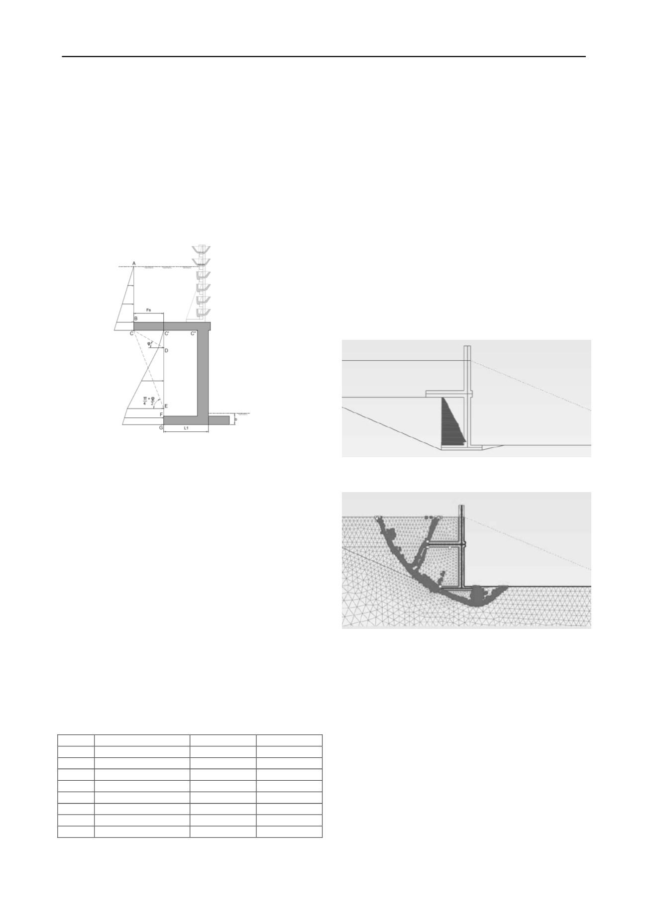
The wall together with the backfill up to the virtual backs
(A-
B and C’
-F) is treated as a monolithic block. Surcharges and
horizontal active soil pressures acting on the virtual backs and
gravity forces may be taken into account. On the lower virtual
back (under the relief floor level), horizontal soil pressures as
described in §1.2 are assumed. This monolithic block is checked
against sliding, overturning and bearing capacity failures in the
ultimate limit state.
It has to be stressed that the above approach is a
simplification of the physical behavior. The physical soil
rupture surface does not follow the two virtual backs, but
corresponds more with wing-shapes.
Figure 5. Virtual backs as in the analytical approach of an inverted
T-shaped cantilever wall with a relief floor.
2 NUMERICAL SIMULATION OF INVERTED T-
SHAPED CANTILEVER WALL WITH RELIEF FLOOR
For the numerical validation of the inverted T-shaped cantilever
wall with a relief floor, two-dimensional finite element code
PLAXIS is used. The Hardening soil model in plane strain is
used to model the soil (Brinkgreve et al. 2002).
2.1
Simulation of excavation stages
Accomplishment of physical modeling, including simulation for
gravity stresses is followed with the calculation program.
Simulation of the entire inverted T-shaped cantilever wall with
relief floor is carried out in a sequence of construction stages. In
each construction stage a sufficient number of calculation steps
are used to obtain an equilibrium-state:
Stage 1 : initial situation (gravity loading, soil with
temporary cohesion)
Stage 2 : excavation till bottom level of the cantilever wall
(soil with temporary cohesion)
Table 1. Soil parameters of sandy soil, silty soil and clayey soil, as used
in the numerical simulations (the stiffness is expressed at a reference
pressure of 100 kPa).
Sandy soil
Silty soil
Clayey soil
γ
unsat
17kN/m³
18kN/m³
17kN/m³
E
ref
oed
22,30.10³kN/m²
6.10³kN/m²
4.10³kN/m²
E
ref
50
22,30.10³kN/m²
9.10³kN/m²
8.10³kN/m²
E
ref
ur
66,90.10³kN/m²
36.10³kN/m²
40.10³kN/m²
m 0,50
0,75
1,00
c’
temp
4kPa
4kPa
4kPa
c’
perm
0,1kPa
2kPa
4kPa
φ’
30°
25°
22°
Stage 3 : construction and back fill of the cantilever wall
till level of relief floor (soil with temporary cohesion)
Stage 4 : Construction and back fill of the relief floor till
final level (final situation, permanent soil parameters, SLS)
Stage 5 : Determination of factor of safety using c-phi
reduction (ULS).
The model simulates 100m (length) by 50m (depth) using
4825 elements (15-noded). The elements around the inverted T-
shaped cantilever with relief floor are highly refined. The
geotechnical behavior is simulated in unsaturated sandy soils,
silty soils and alluvial clayey soils (Table 1).
2.2
Numerical simulation of an inverted T-shaped cantilever
wall in sandy soil
A typical section of inverted T-shaped cantilever wall is
simulated (Figure 1), retaining the soil over 8,6 m of height. The
used geometry implies a L1 = 3,6m and a Fs = 1,9m (Figure 5).
The buried depth of the base slab D is in this case 0,6m. The
used type of in situ soil and the backfill soil are in this example
the above described ‘Sandy soil’.
Figure 6. Horizontal effective soil pressures at the lower virtual back
up to 61,3kPa at stage 4 (c-phi reduction of 1,20).
Figure 7. Positions of elements with a Mohr-Coulomb plastic
behavior in stage 4 (c-phi reduction of 1,20).
The global geotechnical safety, calculated by the c-phi
reduction is 1,20. Figure 7 shows the positions of the elements
which are in the plastic zone of the Mohr-Coulomb law. The
failure surface underneath the foundation level suggests a
failure mode of bearing capacity. As the inverted T-shaped
cantilever wall deforms, failure surfaces, inclined at
π/4
-
φ/2
from the vertical, at the upper and lower virtual backs occur.
This corresponds with the described failure ‘wings’ in §
1.1.
The effective horizontal stresses at the upper virtual back
increases from 0kPa up to 29kPa. At the lower virtual back, the
effective horizontal stresses increases from 2kPa up to 70kPa.
Figure 6
shows that the influence of the relief floor isn’t total :
the relief floor deforms 3cm downwards, causing a small
horizontal effective stress (2kPa) at the top of the lower virtual
back. The mean effective vertical stress at the base slab amounts
to 228kPa.


