1972
Proceedings of the 18
th
International Conference on Soil Mechanics and Geotechnical Engineering, Paris 2013
Figure 2. Bond stress distribution in the fixed length for different stages
of a load test until failure. The area A is the failure load of the fixed
length of the anchor. ( Barley and Ostermayer, 2003).
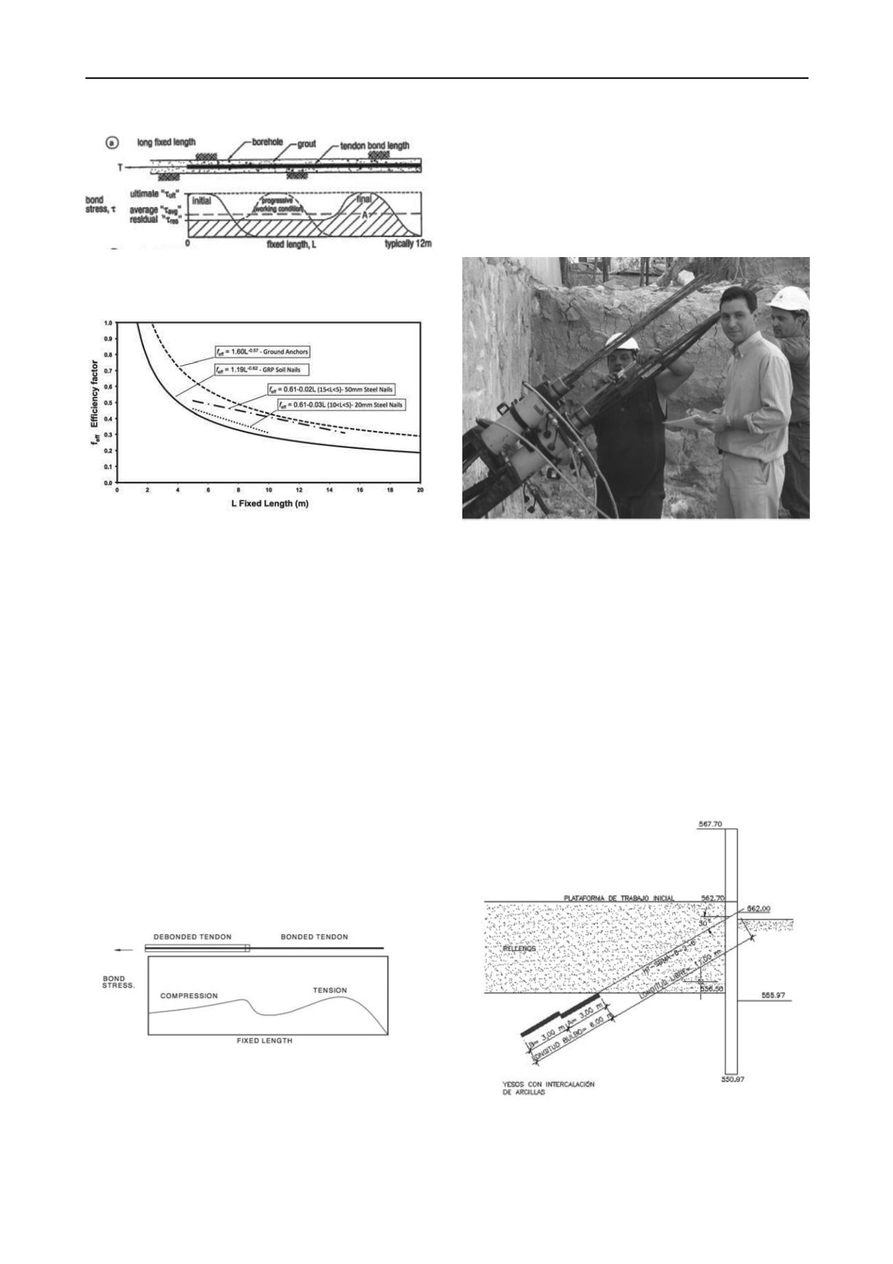
Figure 3. Efficiency factor for Ground Anchors, Steel a GRP Soil Nails
(Barley, 1997)
The ultimate geotechnical capacity of the anchor (T
ult
) is:
T
ult
d
ult
f
eff
L
(2)
This formula does not apply to granular soils where the
capacity to borehole diameter (d) it is not linear and has to be
establish by meter of fixed length.
All load transfer mechanisms from tendon to grout induce
bursting forces in the grout of one degree or another. Generally,
the greater the mechanical locking effect (end plate or major
deformations) the greater the bursting forces. It follows that the
shorter the tendon bond length the greater the mechanical
locking to allow the potential transfer of full tendon load
capacity. However, this can only be effected where the ground
or strong rock will provide adequate confinement of the grout
column to prevent bursting failure. So to reduce the inefficiency
in load transfer (entire fixed length in shear and tension) it is
appropriate to utilize tendon bond lengths long enough to
eliminate the risk of bursting failure yet as short as possible to
gain maximum efficiency from grout/ground bond (Figure 4).
The high values of bond stress at the grout/ground interface
results from the dilatancy effects of the soil in the shear zone,
and interlocking at the rough interface, all as a consequence of
an increase in radial normal stress.
Figure 4. Probable bond stress distribution in compression and
combined shear and tension.
3.2
Prelimary tests
Where preliminary trial anchors are tested to failure, each unit
anchor yields its own value of ultimate bond capacity and hence
more intensive data than conventional test anchors. The in situ
testing of many of these multiple anchors with variable unit
lengths has therefore recently extended the knowledge and
understanding of the tendon/grout/ground bond mechanism. The
SBMA system has been utilized in permanent anchors and
temporary anchors (including those with removable tendons).
Test anchors of length 2.5 to 5 metres may easily be taken
to failure to establish the ultimate bond stress of that length and
then the fixed length of production anchors accurately, designed
to provide the required factor of safety. In the trials it is
important to control the grouted length tested.
Figure 5. Trial research test with multiple synchronized hydraulic jacks
in Parking La Vega, Murcia, 2005.
4.
CASE HISTORIES
4.1
La China Stormwater management pond (Madrid)
In carrying out the excavation depth of 15.0 meters, were
implemented temporary SBMA anchors of 2000 kN design
load, using four units in the soil strata called "Peñuela" (gypsum
with interbedded clays). The system was used always in
combination with an injection unit located in each bulb known
in spanish specification as IR that involves a postgrouting
procedure and each units had 3x0,6” steel strand.
Research trials conducted according to the standard UNE
1537, allowed to change the original traditional ground anchors
design, for less multiple anchors witn increased load and
efficiency.
Figure 6. Section of diaphragm wall with trial anchor test TA2.


