1969
Technical Committee 207 /
Comité technique 207
gravel pool, proposed in the preliminary design, uplift loads are
proposed to be taken by tension piles under the foundation.
As described in the previous sections, the site is located in a
densely populated urban zone and there are important
neighboring infrastructures around the plot. In order to
minimize the lateral displacements to be realized during
excavation implication of the proposed top down procedure was
very effective and superior compare to strutted excavation.
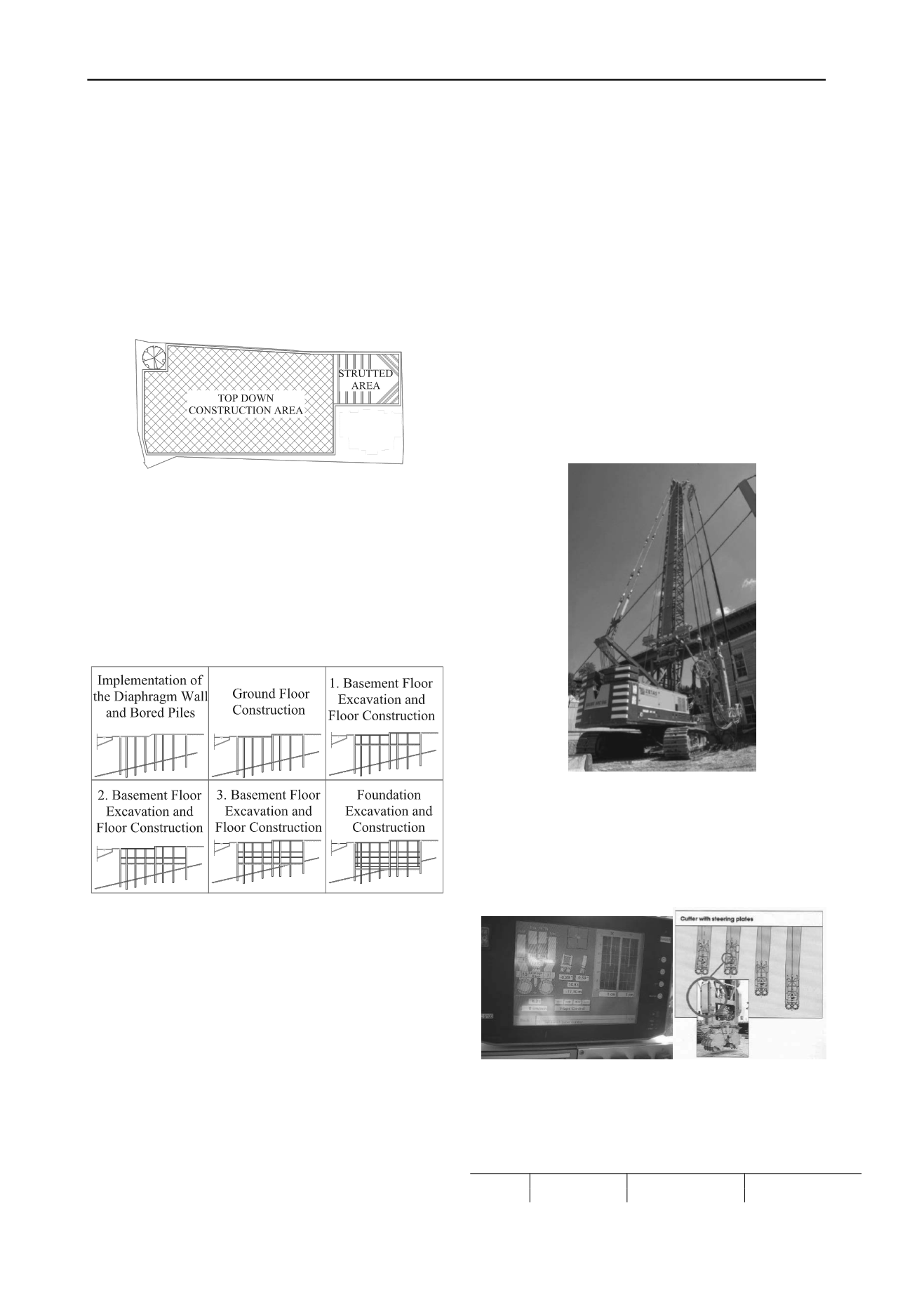
In the proposed top down method permanent diaphragm
walls and piles are to be constructed prior to excavation works.
Later ground level r. c. floor will be constructed except the part
behind the Hatice Sultan residence (Figure 6).
Figure 6. Top Down Construction Area
Soil under the ground level floor will be excavated phase by
phase until the bottom elevation of foundation. In parallel to
excavation works 1st basement r. c. floor will be constructed.
The part of limited excavation plot behind the Hatice Sultan
Residence will be supported with steel struts to provide space
for ramps which will be used for the transportation of the
excavated material. Top down construction steps will continue
similarly as 2nd basement floor 3rd basement floor and
foundation respectively (Figure 7).
Figure 7. Top Down Construction Steps
Groundwater seepage into the excavation site is evaluated
by seepage analysis and optimum socket length in to the
bedrock is determined as 5.0 m. Also settlements due to the
lowering groundwater table are estimated and found to be less
than 18 mm which is considered as tolerable for the existing
structures.
Bored piles are designed to be used as compression and
tension members depending on the loading conditions.
Therefore, piles which will act as permanent columns of the
underground structure are extended into the bedrock having
minimum socket length of 6.0 m basedon the result of pile
tension test conducted at the site in order to satisfy the most
critical tension loading condition under the uplift forces.
Tension capacity of the piles are estimated and taken into
account against uplift forces.
In the top down construction, floor and foundation
reinforcements will be integrated into the permanent diaphragm
wall and piles with the aid of additional link reinforcements
which are already placed in these elements. Details of these link
reinforcements are given in the next section.
After the top down construction steps the limited area
behind the Hatice Sultan Residence will be constructed with
conventional method from bottom to top in parallel to
dissembling the steel struts. Special water-proofing works will
also be implemented under the foundation and on the
constructive inner wall during the down to top construction
steps.
6 CONSTRUCTION STAGE OF DIAPHRAGM WALLS
At the time of paper submission, diaphragm wall construction
was just completed and preparations have been realized to
initiate the piling works. Therefore only diaphragm wall
construction stage would be covered within the paper.
To implement the diaphragm wall in required socket lengths
in the bedrock formation, hydrofraise machine was mobilized
for this project having 81 kNm max. torque per gear box, and 25
rpm max. revolution, with a max cutting depth capacity of 70m
(Figure 8).
Figure 8. Diaphragm Wall Machine, Hydrofraise-Cutter
Another reason of implementing the hydrofraise-cutter
machine was to provide a better verticality control during the
construction of the permanent diaphragm walls. The verticality
was monitored parallel to diaphragm wall excavation and
direction of the cutter controlled with the help of the flaps on
the edges (Figures 9a and 9b).
Figures 9a and 9b. Verticality Control System
During the soil investigations encountered maximum UCS
values of the bedrock are given at the Table 2 below.
Table 2. Unconfined Compression Strength (UCS) values- Mpa
Intrusive Dyke
Sandstone
Shale Sandstone
Min.
Max.
Min.
Max.
Min.
Max.
UCS
Value
0.7
65
3.6
160
1.0
67


