1966
Proceedings of the 18
th
International Conference on Soil Mechanics and Geotechnical Engineering, Paris 2013
parameters. Their recommendation is also to make a computer
code using the detailed described procedure and solve the
problem in question explicitly. The resulting force from the
integration along a rupture line consists together with simple
zone ruptures the backbone of the Danish earth pressure theory,
and should by no means be questioned here.
When a quantity is greater than zero, the predicted value is
on the safe side. When a quantity is 1 the corresponding ratio is
2.7. If
A,
or
M
is zero the quantity is minus infinity but plotted
on the frame of the diagram.
It should be mentioned that the procedure involves two
calculations: (i) a calculation with both
P
and
G
(Figure 2), and
(ii) a calculation with
G
alone. The influence of
P
is found by a
subtraction of the two vectors. As
G
is great compared to
P
the
latter is poorly determined and also problems with the validity
of supposition as assumed here will distort the result.
A study of Figure 9 shows that the proposed procedure is
superior to the empirical procedure and the fit is surprisingly
accurate taking into account the complexity of the problem.
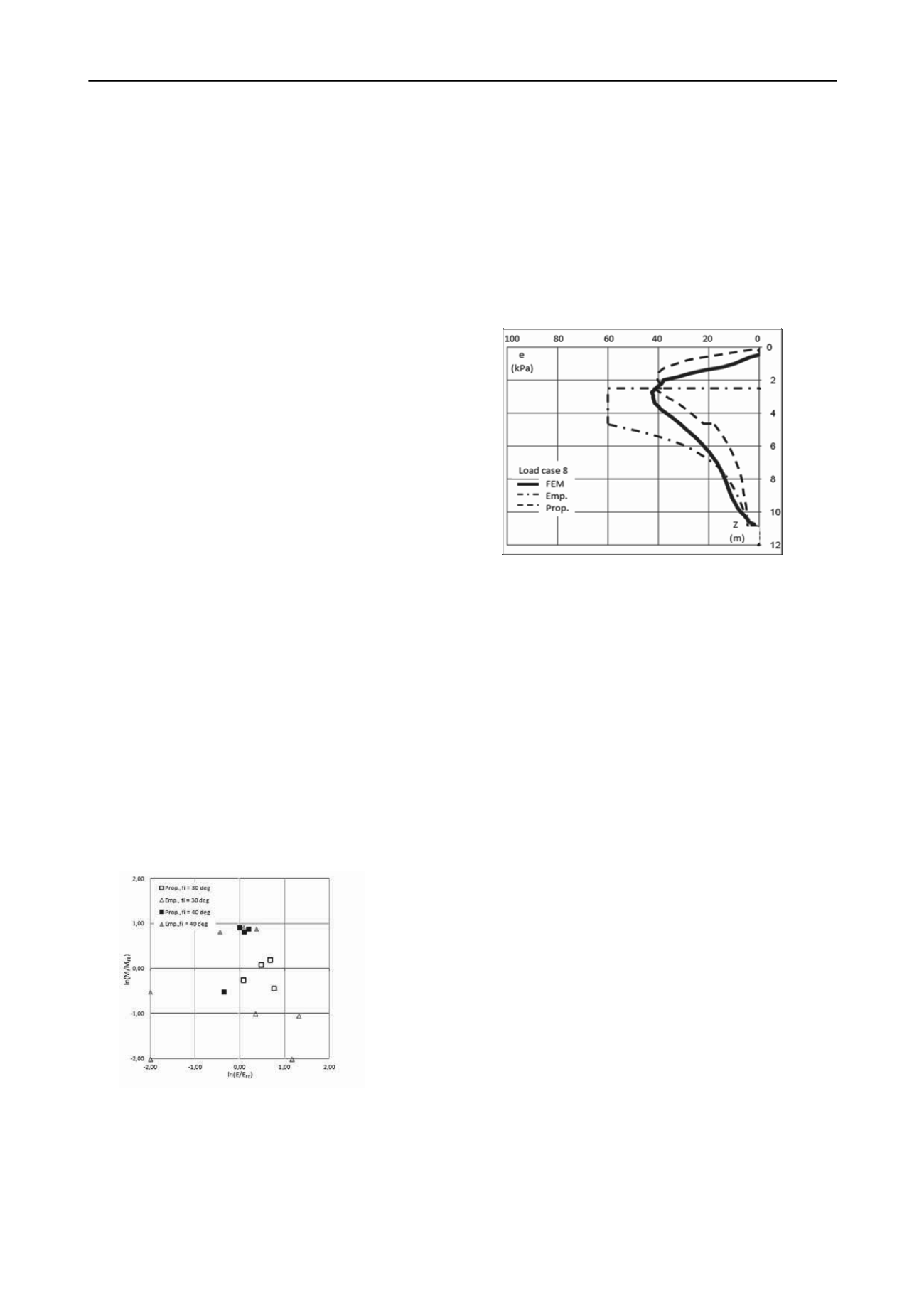
In order to offer a qualitative impression of the results a
single distribution from the FE calculations is shown in Figure
10. This distribution is supplemented with distributions from
two other methods (Empirical and Proposed).
Another problem is connected with the integration of the
Kötter’s equation. The only contribution to a change of the
ambient stress condition is caused by the unit weight. However,
the rupture line will pass through domains in the soil much
differently affected by the partial loaded surface.
In every case the method will not provide the distribution of
the pressure which is imperative especially to determine the
moment in the wall in the anchor level.
9
PROPOSED PROCEDURE
When a procedure to assess the influence of a partial loaded
surface it should be taken into consideration that the proposed
distribution should converge to the distribution usually applied
for a fully loaded surface.
The procedure proposed is:
Calculate the elastic distribution (
e
e
(
z
)) using the
equations in Figure 5.
Calculate the distribution usually used for a fully loaded
soil surface. Use only the part of this distribution
corresponding to the uniform part of the distribution
(
e
p
(
z
)) shown in Figure 4.
Figure 10, Normal pressure distribution (e) from FE calculations
compared with other methods (Empirical, Proposed) for a single load,
(Load Case 8).
11
CONCLUSION
The final distribution is:
e
(
z
) =
W
*
e
p
+ (1-
W
)*
e
e
(
z
),
where
W
is a weight function
W
= 1.5*(
F
-0.167)-
2*(
F
-0.5)
3
and
F
= 0.8*
b
/
h
.
A procedure to calculate the pressure distribution has been
proposed and has proved an excellent fit with results from FE
calculations. The procedure is based on the theory of elasticity
where the assumption of an immobile wall is justified by the
high rotation point. The result converges to the usually applied
when the entire surface is loaded.
10
VERIFICATION
The benchmark for the verification is chosen as the results of
the FE calculations. As before mentioned it is difficult to
characterize the distributions by simple means. We have here
focused on the usage of the distribution: (i) to calculate the
anchor force (
A
), and (ii) to calculate the moment in the wall in
the anchor level (
M
).
12
ACKNOWLEDGEMENT
The authors acknowledge GEO-Danish Geotechnical Institute
for the financial support of the project.
13
REFERENCES
Boussinesq, J. 1885,
Application des potentiels a l’etude de équilibre et
du mouvement des solides élastiques
. Gauthier-Villars, Paris.
Brinch Hansen J. 1953,
Earth Pressure Calculation
, Danish Technical
Press, Copenhagen.
Coulomb CA. 1776, Essai sur une application des rèles des maximis et
minimis a quelques problems de statique
. Memoires Acad. Royale
des Sciences
, Vol. 7. Paris.
Denver H., Kellezi L. 2011, Earth pressure from a nearby building on
sheet pile walls.
Proc. 17
th
European Conf. Soil Mechanics and
Geotechnical Engineering
. Athens.
Mortensen N.,Steenfelt J.S. 2001, Danish plastic design of sheet pile
walls revisited in the light of FEM,
Proc. 15th Int. Conf. Soil
Mechanics and Geotechnical Engineering.
Istanbul.
Plaxis, 2011,
FE Code for Soil and Rock Analyses
, User’s Manual, A.A.
Balkema, Rotterdam.
Steenfelt J.S., Hansen B. 1984, Sheet pile design earth pressure for strip
load,
J. Geotecn. Engrg. ASCE
Vol. 110, No. 7.
Figure 9, Accuracy of the methods (Empirical, Proposed vs. FE).
The anchor force is estimated as the part of the distribution
above the depth
z
equal to double the height of the wall above
the anchor. This procedure excludes the results found by the
theory of plasticity to be represented. The quantities ln(
A
/
A
FE
)
and ln(
M
/
M
FE
) are made where the denominators are the results
from the FE calculations. These quantities are plotted against
each other in Figure 9 for load cases (1-4) and (6-9).


