1996
Proceedings of the 18
th
International Conference on Soil Mechanics and Geotechnical Engineering, Paris 2013
2.1
Geological & Geotechnical Conditions
The geology of the site mainly consists of Carboniferous aged
Trace Formation’s intercalation of sandstone – siltstone layers.
The bedrock is overlain by weathered particles of the Trace
Formation in clay matrix with thicknesses varying between 3 ~
4 m. Finally the site is covered with artificial fill with a
thickness of ~2 m. The bedrock is divided in to two fictitious
layers at a depth of 14 m according to the increasing rock mass
quality. Except leakage water from the discontinuities and
fractures, no groundwater table was encountered at the site. The
proposed stratigraphy and the engineering parameters used in
modeling are presented in Table 1.
Table 1. Proposed stratigraphy and engineering parameters
Layer
Fill
Residual Zone
Bedrock-1 Bedrock-2
Thickness (m)
2
5
7
-
c (kPa)
0
1
5
10
(°)
25
30
35
38
(kN/m³)
18
20
22.5
23
E (kN/m²)
5,000
25,000
100,000
150,000
0.35
0.30
0.28
0.25
2.2
Design Philosophy
Since the construction of the pedestrian tunnel and shaft were
ongoing at the time, the initiation of the phased construction
model had to be started with simulation of these structures. The
design work was aiming to find out the effects of the deep
excavation on the tunnel and shaft structures. In order to detect
the magnitude (after initial phase) and variations of the section
forces together with the deformations of the tunnel and shafts’
temporary support system throughout the deep excavation,
demounting and basement construction stages, the shotcrete
facing was modeled with shell elements.
The deep excavation support system was designed
contiguous (without a gap) to the basement walls that will be
constructed after the completion of the deep excavation. This is
mainly due to the clients’ demand for minimum space loss. This
philosophy turned in to an advantage for the adjacent tunnel and
shaft, since every constructed basement floor constituted a rigid
support to the shoring system, hence the effects of demounting
stages could be minimized on tunnel and shaft.
Both the 2D and 3D finite elements models were constituted
in compliance with in-situ construction steps (tunnel & shaft
construction, staged deep excavation procedure, staged
basement construction and demounting of the steel struts).
The steel struts, piles of shoring system, shotcrete facing and
the rockbolts were modeled as linear elastic materials. The
properties of these linear elastic materials are given in Table 2.
All struts used were tubular steel with a thickness of 10.3 mm.
Table 2. Elastic and rigidity variables
Material
E (kN/m²) D Spacing (m)
d Diameter
Micropiles
2.5E7
0.60
30 cm
0.20
Shotcrete
2.0E7
cont.
20 cm
0.20
Steel struts
2.1E8
3
16” ~ 32”
0.28
Rockbolts
1E7
1.5
51 mm
0.28
2.3
2D FE Analysis
General approach to model a deep excavation in geotechnical
engineering is to execute Limit Equilibrium stability analysis to
get the satisfactory factor of safety and a FEA to check the
compliance of deformation criteria. Since 2D FEA is a fast and
effective design tool, the same methodology was used for the
subjected project.
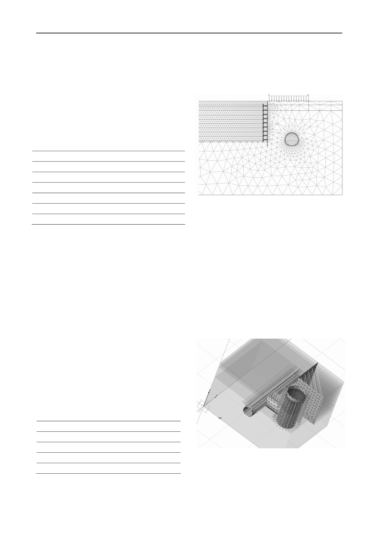
The 2D FE model at the adjacent tunnel location is given in
Figure 2.
Figure 2. 2D FE model from tunnel section
Deformation analyses were carried out with commercial
software package of PLAXIS. Mohr Coulomb material model
was used for the design based on the expertise of deep
excavation designs and their feedback from in-situ performance,
in similar geological circumstances which is very widespread in
Istanbul.
2.4
3D FE Analysis
A 3D FE Analysis had to be conducted in order to simulate the
interaction between the deep excavation works and
tunnel&shaft. The main goal of the 3D modeling study was to
establish an appropriate excavation system and sequence, hence
only the related part of the system was focused in the analysis.
By this means, the processing time in such a complex model
could be reduced to a reasonable level. As it is in 2D FEA, also
Mohr-Coulomb material model was used in the 3D FEA. All
engineering parameters were kept same.
The 3D FE model is given in Figure 3.
Figure 3. 3D FE model from with nearby tunnel and shaft
3 RESULTS FROM THE ANALYSES
The main purpose of this modeling study was to find out the
interaction between the tunnel&shaft structures with (and
during) the deep excavation works. Therefore, the specific
values (bending moments, shear forces, normal forces, and


