2001
Technical Committee 207 /
Comité technique 207
3 ANALYTICAL SOLUTIONS
An analytical method to simulate the penetration procedure for
suction caisson in clay has been proposed by Houlsby and Byne
(2005b). The friction between internal caisson wall and internal
clay and that between external wall and external clay were
considered separately by using different friction coefficient
(different
α
value). The self-weight penetration and suction
assistant penetration have been made a clear distinction. As the
the self-weight penetration is very small in our 1-g model tests,
only the suction assistant penetration process is discussed in this
paper.
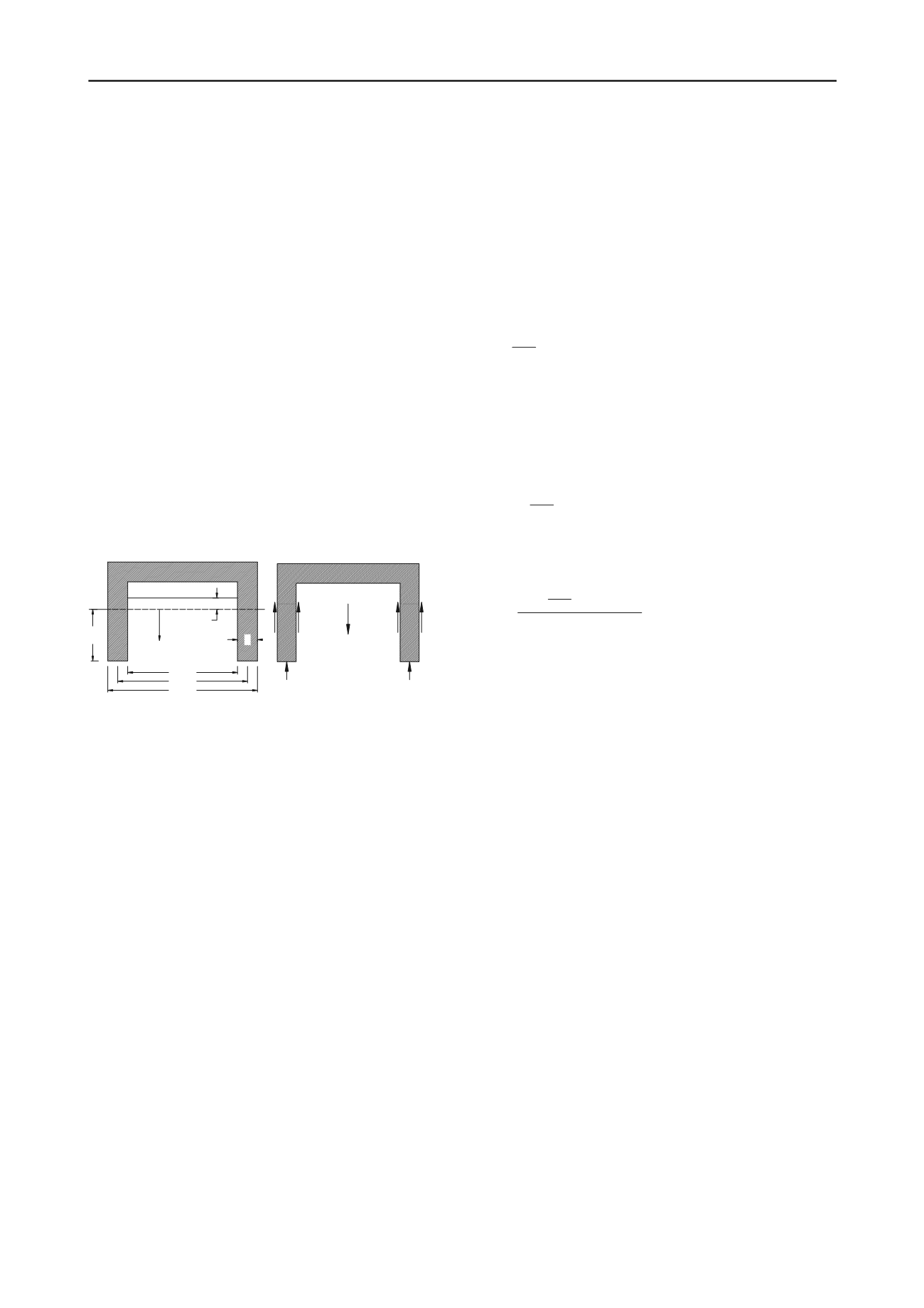
A simplified cross-section of the suction caisson is shown in
Figure 6. The vertical coordinates, measured at a depth below
the mud line, is set up with
z
. The inside, outside and average
diameters of the caisson are represented by
D
i
,
D
0
,
D
respectively. Therefore,
D
i
=D
0
-
2
t
and
D
= (
D
i
+
D
0
)/2 where
t
is the thickness of the caisson wall. The total height of the
caisson is
L
and height embedment into the seabed is
h
. The soil
plug higher than the mud line inside of the caisson is denoted as
h
p
. The unit weight of water is
γ
w
and that of soil is
γ
.
As illustrated in Figure 6(b), the total effective weight of
suction caisson is presented as V'. The side frictions between
soil with outside and inside of the caisson are written as
Q
in
and
Q
out
, respectively. The end bearing capacity on the tip of suction
caisson is defined as
Q
tip
.
D
D
D
h
t
Mudline
z
i
0
h
p
Soil plug heave
V'
Q Q
Q
in
out
tip
(a) Parameters definition (b) Free body diagram
Figure 6 Cross section of suction caisson (Modified after Houlsby and
Byne, 2005b)
When the caisson penetrates into the soil, a bearing capacity
failure will occur around the wall tip. It is assumed that the soil
plug is mainly due to these displaced soil flow into the caisson.
We make the simplifying assumptions that: (a) there is a volume
of clay,
V
s
, flows into the caisson because of the replacement of
caisson walls,
V
c
, and
V
s
=mV
c
; (b) the flowed clay does not
change the original unit weight of clay within the caisson; and
(c) the flowed clay forms the soil plug with its height shown in
Eq. (1). These assumptions were especially valid for the suction
caisson installed in clay which have already been verified by
model test results (Whittle et al., 1998), prototype behavior
(Colliat et al., 1996), and finite element analyses (Andersen and
Jostad, 2002; Andersen and Jostad, 2004). The values of
m
will
be calculated using the model test results.
2
2
0
( /
1)
p
i
h m D D h
(1)
For the case of suction caisson installation in clay, the
calculation neglects the effect of the applied suction pressure
and the side frictions along the caisson walls. Then this
procedure can be treated as undrained conditions. Therefore, the
side frictions are calculated by applying a factor
α
to the value
of the undrained strength (
α
-method), i.e.
Q
in
= hα
i
s
ui
(
πD
i
)
and
Q
out
= hα
0
s
u0
(πD
0
)
where
s
u0
is average undrained strength
between mud line and depth
h
. If the undrained strength of clay
increased along depth linearly, i.e.
s
u
=s
u1
+ρz
, the average
undrained strength of soil,
s
u0
, can be calculated as
s
u0
=s
u1
+ρh/2
where
ρ
is the coefficient of undrained strength increasing.
Similar calculation method can also be applied to the internal
undrained strength,
s
ui
. The bearing capacity on the tip is
calculated according to the standard bearing capacity
calculation, i.e.
σ'
tip
= γ'hN
q
+ s
u2
N
c
and
s
u2
=s
u0
+ρh,
where
N
c
is
the capacity factor for a deep strip footing in clay (a typical
value of 9 may be adopted) and
N
q
=1 for undrained analysis.
During the suction assisted penetrations, the driving force is the
weight of suction caisson and applied suction pressure. The
resistance to the caisson is calculated as the sum of the side
frictions (
Q
in
+
Q
out
) and the end bearing capacity on the tip
(
Q
tip
). The force equilibrium along the vertical direction yields
the following equation:
2
0
0 0
0
2
'
(
)
(
) (
)
( ) ( '
)(
)
4
u
p i ui
i
u c
D V s
h s D h h s D h s N Dt
(2)
The internal and external side frictions calculated by (
h+h
p
)
α
i
s
ui
and
hQ
out
α
0
s
u0
may be assumed to have the same magnitude.
This is reasonable as the internally remold clay will have a
lower undrained shear strength and a lower coefficient of side
friction (Andersen and Jostad, 2004). Then Eq. (2) can be
further simplified as follows:
2
0
0 0
2
'
(
) 2
( '
)(
)
4
u
u c
D V s
h s D h s N Dt
(3)
The penetration depth
h
can be derived from Eq. (3) and shown
as follows:
2
0
2
0 0
'
(
)
(
)
4
2
'(
u c
u
D V s
s N Dt
h
s D Dt
)
(4)
4 COMPARISON BETWEEN THE TWO METHODS
It should be point out that the analytical method for caisson
penetration is only applicable when the caisson is penetrating
into clay with a constant velocity. Then the driving forces and
resistance forces can be treated as balanced during each
calculation step. The results shown in Figure 4, the penetration
depth versus time curve is almost in a linear relationship. The
comparisons between these two sets of results were made by
assuming the caisson was penetrated into the clay in a constant
speed or the forces in each calculation step were balanced.
In the following calculation, the tested vacuum pressures
were taken as inputs. This procedure maybe not the way for
engineering designing but could be used to verify the accuracy
of this theoretical method. The comparison could also give a
way to evaluate the key design parameters for caisson
designing. The average undrained shear strength of soil bed
used for calculation was 13
kPa
as discussed in section 2.1. The
values of
N
c
and
N
q
for undrained analysis were adopted as 9.0
and 1.0, respectively. The average unit weight of soil bed is
12.3
kN/m
3
which can easily be derived from
w%
(42.7%) and
G
s
(2.61). The total weight of concrete caisson is 0.272
kN
(27.2×10
kN
).
The model test results and the analytical results for the
displacement of suction caisson are compared in Figure 7. It can
be seen that when
α
=0.72, the two sets of results agree well with
each other. The analytical results show that the penetration of
suction caisson needs a minimum driving suction pressure.
However, the model tests show a much smaller value.
Furthermore, the penetration procedure for model No. 2 was
delayed (start time of
t
=25
s
) comparing to model No. 1 (starting
time of
t
=13
s
) because the applying speed of vacuum pressure
for model No. 2 is lower than that for model No. 1.
The comparison between the theoretical and the model test
results regarding the heave of soil plug is shown in Figure 8.
The analytical model indicates that a minimum vacuum pressure
is required for the soil plug to start to heave as there is no plug


