2032
Proceedings of the 18
th
International Conference on Soil Mechanics and Geotechnical Engineering, Paris 2013
(two strands each) of 2.2 m bond length were not installed into a
borehole as independent elements but were placed into the joint
corrugated PE duct (type
RCP/D-Z
with strand free lengths of
28 m, 30.4 m and 32.8 m),
•
anchors with variable stiffness of bond length
after the
patent of Škrabl, 2004, with the tendon combined of three
anchor units (2 strands each), with strand free lengths of 28.0 m,
30.4 m and 32.8 m, and with strand bond lengths of 7.0 m, 4.6
m and 2.2 m (type
RCP/D-I
).
3 IN-SITU TESTING
The test field has been located at the level of the middle berm of
a larger retaining wall, where load-bearing stratum consists of
marl and silty marls with thin lenses of siltstone and sandstone.
A total of 18 anchors were installed: three reference RCP/D
anchors and five anchors of each alternative type (RCP/D-K,
RCP/D-Z and RCP/D-I). Boreholes, deflected 15° downwards,
were drilled with a chisel (
∅
140 mm) using air-flushing for the
removal of drill spoil. The ratio of 6-strand anchor steel cross-
sectional area to cross-sectional area of the borehole equaled
5.5% of the theoretical cross-sectional area of the borehole. The
appearance of moist in the ground was repeatedly detected in
the region of the anchor bond lengths. Cement grout with w/c
ratio of 0.42 was used for grouting within the PE encapsulation
as well as for the collar of the borehole with an average grout
consumption of about 17 dm
3
/m
1
.
At in-situ testing individual strands were tensioned with
monostrand jacks, connected to a joint hydraulically
synchronized system (Fig. 2)
.
An electrical load cell was used
for the precise adjustment of stressing forces. Extensions and
creep behavior of strands were measured with digital
displacement transducers, attached on the monostrand jacks.
Figure 2. Test setup for simultaneous stressing of all strands of
prestressed ground anchors using monostrand jacks.
As a measure for the assessment of load-bearing
characteristics of anchor bond lengths creep displacement rate
k
was used (Ostermayer, 1975):
=
2
1
⁄
(1)
where
s
1
and
s
2
are head displacements at times
t
1
and
t
2
,
respectively. For the failure of anchor bond length the critical
creep displacement rate
k
crit
= 2 mm was used.
All reference anchors and one anchor of each alternative
type were tested up to the maximum test load
P
pv
= 1254 kN (80
% steel tensile strength
R
m
) or until failure of anchor bond
length was reached (
investigation test
- IT). Other alternative
anchors were tested using the same procedure, except that the
test was stopped at the first sign of anchor bond length failure,
i.e. as soon as
k
crit
appeared (
comprehensive suitability test -
CST). All test field anchors were tested according to the loading
procedure and methodology for IT as described in Swiss
standard SIA 267/1, which is very similar to test Method 1 of
standard EN 1537: each anchor was loaded in eight incremental
cycles from a datum load
P
a
= 150 kN (10 %
R
m
) to the
maximum test load
P
pv
. The increments of strand extensions
were measured at the end of specified time intervals, which
were used for the evaluation of
k
values. Individual strand
extensions as well as average extensions for all strands of the
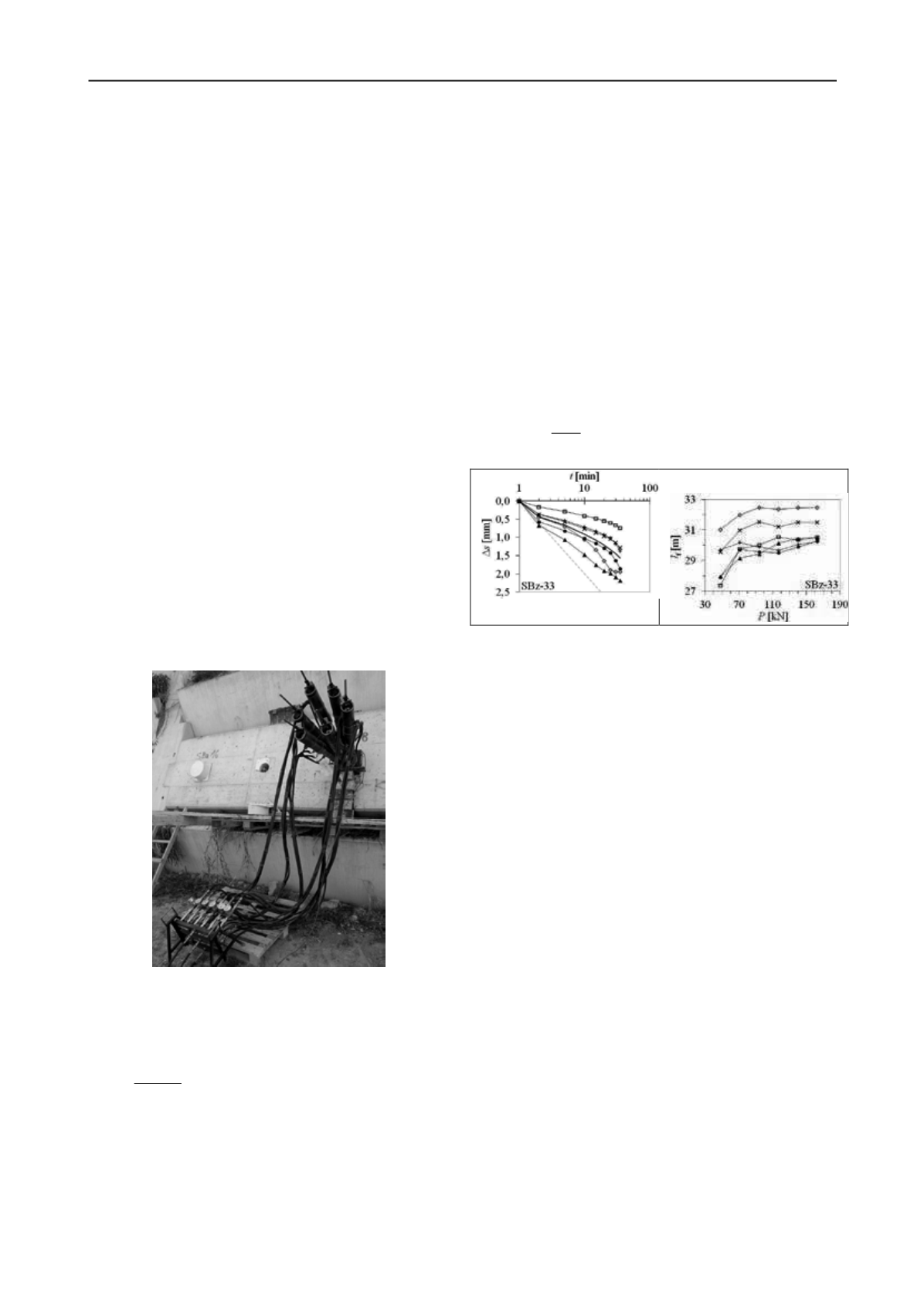
RCP/D-I anchor SBZ-33 at load level
P
6
= 978 kN of CST are
presented on the left diagram of Fig. 3. The right diagram shows
the development of apparent free lengths
l
f
of individual strands
during the same CST, which is based on the measured elastic
displacement
∆
s
el
at load decreasing from current level
P
i
to the
initial level
P
a
, knowing the characteristics of the tendon (cross-
section area
A
p
and modulus of elasticity
E
p
):
f
=
∆
el
a
p
p
(2)
Figure 3. Measured increments of displacements of the anchor SBz-33
(type RCP/D-I) at load level
P
6
of CST (left), apparent free lengths of
individual strands
l
f
during CST (right).
The behaviour characteristics of anchor bond length could be
recognized only on the basis of strand extensions, measured on
displacement transducers, fixed on the monostrand jacks. The
problem is that due to the limited amount of data and the
inability of physical insight into the bond lengths deep in the
load bearing stratum, we cannot always directly link measured
extensions with creep displacement rate
k
of the bond length
(i.e. it is not necessary that each measured strand extension
actually originates from the bond length deterioration).
Therefore, in the analysis of the in-situ test results it is
recommendable to compare the
k
values of individual strand
with the
k
values of other individual strands of the same tendon,
with
k
values of anchor units (average of two strands, only at
types RCP/D-Z and RCP/D-I), with the average
k
values of all
strands, as well as with the permanent displacements
∆
s
bl
and
apparent free lengths
l
f
, obtained after each loading stage. In
order to prevent sudden failures of bond lengths at CST, an
appropriate software tool was prepared to enable simultaneous
recording and evaluation of the most important behaviour
parameters of an anchor during in-situ test.
4 ANALYSIS OF RESULTS OF THE IN-SITU TESTING
There are several possible failure mechanisms at the anchor
bond length, which occur at the IT of prestressed ground anchor
with a comprehensive corrosion protection: inside or outside the
PE corrugated duct, under some circumstances it may also come
to the rupture of PE duct. The types and incidences of individual
mechanisms depend on the design of bond length and packing
connections at the transition between strand free and bond
lengths, possible surface contamination of the bare strand bond
length, the design, dimensions and distribution of the constituent
components of anchors, local conditions in the ground,
configuration of strands in the bond length, drilling and flushing
techniques as well as specifics of grouting. According to the


