99
Honour Lectures /
Conférences honorifiques
Proceedings of the 18
th
International Conference on Soil Mechanics and Geotechnical Engineering, Paris 2013
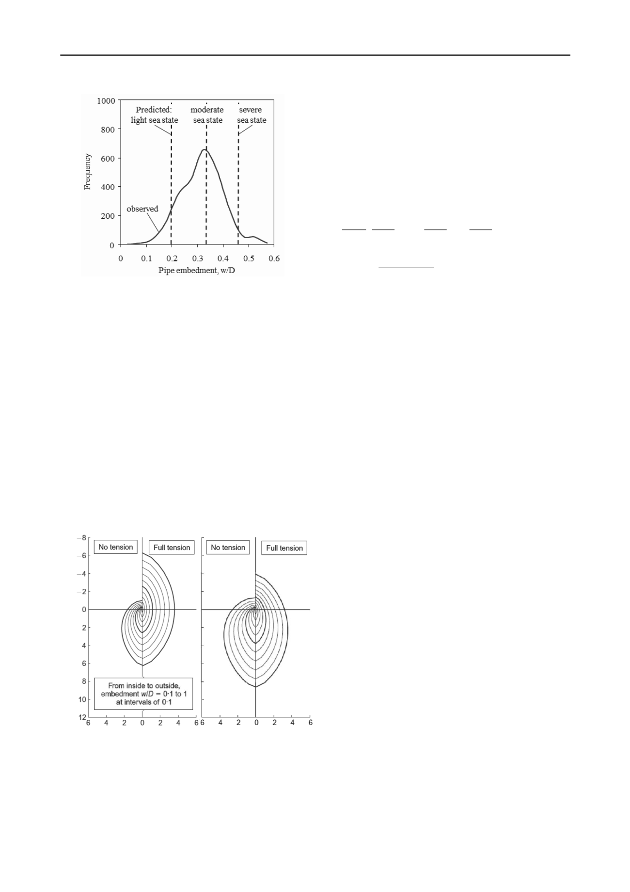
Figure 20 Comparison of predicted and observed pipeline embedment
(from Westgate et al. 2013, Site C).
6.2
Lateral resistance
The lateral resistance of partially embedded pipelines may be
assessed, as for shallow foundations, from failure surfaces in
vertical (V) – horizontal (H) load space. The form and size of
failure envelope depend on factors such as the embedment, the
pipe-soil interface condition (friction ratio,
, ranging between
0 for smooth to 1 for rough; and whether tensile stresses are
permitted), the shear strength profile (ranging from uniform to
varying proportionally with depth) and the relative magnitudes
of effective stress and shear strength.
Theoretical failure envelopes considering some or all of
these variables have been presented by Randolph and White
(2008b: analytical upper bound solutions), Merifield et al.
(2008: finite element analyses) and Martin and White (2012:
closely bracketed finite element based lower and upper bound
plasticity solutions). An example from the most recent of these
is shown in Figure 21, for a fully rough pipeline embedded in
soil with strength proportional to depth, for two different ratios
of effective stress to shear strength gradient (
'/
).
H/
D
2
H/
D
2
V/
D
2
'/
= 0
'/
= 3
Figure 21 Examples of failure envelopes for rough pipelines in soil
with strength proportional to depth (Martin and White 2012).
There is a significant difference in lateral and uplift
resistance depending on the assumption of full tension or no
tension at the pipeline surface. The slight uplift resistance for
the case of no tension is primarily due to soil above the pipeline
for embedment ratios exceeding 0.5. In practice, model test data
indicate that, during lateral displacement, the tensile resistance
on the trailing edge of a pipeline is extremely brittle, so that the
relevant failure envelope reverts quickly to that for no tension.
The theoretical failure envelopes referred to above are based
on ideal, rate independent non-softening soil, and ignore any
local heave (relative to the flat seabed) adjacent to the pipeline.
A more realistic study, based on LDFE analysis, that takes
account of such features was presented by Chatterjee et al.
(2012b). For the particular set of soil parameters investigated,
they derived failure envelopes that were approximately
parabolic, expressed as
2
1
2 1
2
1
2 1
2 1
max
max
max
max
max
where
0
V
H
V
V 1
V
V
V
H
(36)
The quantities
1
,
2
and H
max
/V
max
were found to vary with
embedment according to
D/w 31.0 17.0 V/
H
D/w 87.0 55.0
D/w 89.0 59.0
max
max
2
1
(37)
The failure envelopes allow estimation of the breakout
lateral resistance for any given vertical load ratio, V/V
max
, and
loading path. As a pipeline is displaced laterally it tends to rise
towards the seabed, or plunge deeper, depending on the initial
embedment and vertical load ratio. After sufficient movement it
will reach a steady residual horizontal resistance, H
res
. Pipeline
trajectories during breakout, and a methodology for assessing
the residual resistance ratio, H
res
/V, were also presented by
Chatterjee et al. (2012b).
6.3
Axial resistance
The axial resistance of pipelines is an intriguing problem that, at
face value, would seem to be essentially trivial (a sliding failure
with known vertical load), but in practice turns out to be more
complex. There are three main aspects that need to be
considered (Hill et al. 2012):
The pipe-soil interface friction, which is affected by the
relative roughness of the pipeline coating, and also the
magnitude of the normal effective stress. At the very low
effective stresses (generally less than 5 kPa) applied by deep
water pipelines, the effective stress failure envelope shows
significant curvature.
The cylindrical geometry of the pipeline, which for any
given embedment leads to integrated normal effective
stresses around the pipe-soil interface that exceed the
pipeline weight by a so-called ‘wedging factor’.
Excess pore pressure development at the pipe-soil interface,
which leads to a strong dependence of the axial resistance
on the velocity and cumulative axial displacement.
The first of these requires appropriate experimental data,
typically obtained using direct shear devices that have been
adapted for very low normal stresses. Analytical solutions can
provide a theoretical basis for the other aspects, and these are
discussed here.
The basis for estimating the wedging factor,
, due to the
cylindrical pipe surface is illustrated in Figure 22. Drawing on
the classical solution for the stresses due to a line load acting on
the surface of a homogeneous elastic half-space, a cos
variation of the normal effective stress may be assumed (with
the magnitude of the induced ‘radial’ stresses decaying
inversely with radius from the pipe centre). Integrating the


