89
Honour Lectures /
Conférences honorifiques
Proceedings of the 18
th
International Conference on Soil Mechanics and Geotechnical Engineering, Paris 2013
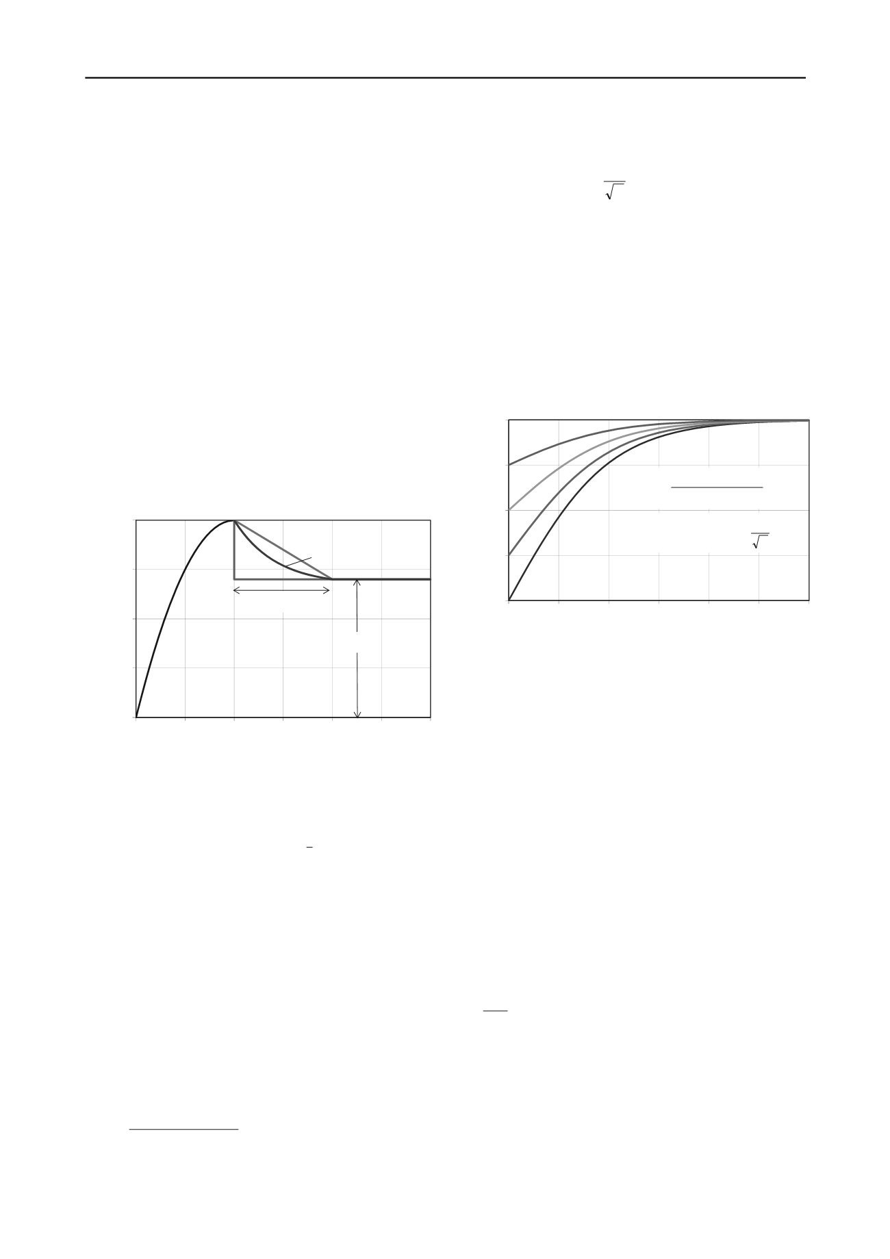
2.4
Post-peak strain softening
Axial compression or extension of the pile leads to non-uniform
mobilisation of shaft friction down the length of the pile, with
slip between pile and soil generally being initiated at the
mudline and gradually propagating down the length of the shaft.
Any strain softening in the load transfer response will therefore
allow a form of progressive failure, such that the maximum
shaft resistance will be less than the ideal value for a
hypothetical rigid pile.
Alternative forms of load transfer curve are shown in
normalised form in Figure 4, with the linear degradation to
70 % of peak shaft friction being consistent with API and ISO
design guidelines for clay. A difficult consideration is how to
scale the degradation response from laboratory to field scale,
and the extent to which a given degree of degradation should be
based on absolute displacement or displacement scaled to pile
diameter. Even though the degradation occurs locally at the
pile-soil interface, the surrounding stress field (and even the
width of the main shearing zone) is affected by the pile size, so
that scaling with pile diameter seems at least partly justified. In
some soil types, much more significant degradation can occur
(Erbrich et al. 2010), possibly occurring over rather greater
displacement than the 1 % of pile diameter suggested in
offshore design guidelines.
0
0.25
0.5
0.75
1
0
0.5
1
1.5
2
2.5
Normalised shear stress,
/
f
Normalised displacement, w/w
f
3
w
res
/w
f
linear
fully
brittle
exponential
Figure 4 Alternative forms of post-peak softening in axial load transfer
curves.
The actual shaft resistance, Q
s
, may be expressed as a
proportion, R
pf
, of the ideal shaft capacity, Q
shaft
:
f
shaft
shaft
pf
s
DL
Q
where
QR Q
(10)
The value of R
pf
will be a function of the degree and brittleness
of strain softening and the compressibility of the pile.
An analytical solution for the extreme case of ‘ìnstant’ strain
softening was given by Murff (1980), who expressed the
reduction factor, R
pf
, as a function of the strain-softening ratio,
=
res
/
f
, and a non-dimensional pile compressibility,
3
. The
latter quantity may be shown to be identical to
L. For strain
softening over a finite distance,
w
res
, Randolph (1983)
proposed an alternative non-dimensional pile compressibility or
compliance, C, substituting the displacement to failure, w
f
, for
the displacement from peak to residual,
w
res
. Numerical
experiments suggest, however, that a more robust measure of
pile compliance, in respect of progressive failure, is the total
displacement to residual, i.e. w
f
+
w
res
, with C defined as:
res
f p
2
f
w w EA
LD
C
(11)
With this definition, the reduction factor can be approximated as
C
1 tanh
1 ~ R
pf
(12)
as illustrated in Figure 5.
This expression provides an initial estimate to assess the
extent to which progressive failure may reduce the net shaft
resistance. The actual reduction factor will depend on the
precise form of the load transfer curve, particularly in respect of
degradation, and should therefore be evaluated through
numerical analysis. A detailed investigation of the performance
of steel jacket structures in Gulf of Mexico hurricanes found
that the one case where axial pile failure occurred could be
explained by progressive failure using the API (2011)
recommended form of load transfer curve with degradation to
70 % of peak friction (Gilbert et al. 2010).
0
0.25
0.5
0.75
1
0
0.5
1
1.5
2
2.5
3
Reduction factor, R
pf
Inverse of square root of pile compliance, C
= 0.75
= 0.5
= 0.25
= 0
res
f p
2
f
w w EA
LD
C
C
1 tanh
1 ~ R
pf
Figure 5 Reduction factor due to progressive failure.
2.5
Lateral pile resistance – clay
Design methodology for the lateral response of piles is almost
universally based on load transfer approaches. These are well-
suited to capture the significantly non-linear soil response,
particularly in the upper few diameters of the pile. However, the
proposed load transfer curves are labyrinthine in formulation
and with no obvious link to any analytical basis. Jeanjean
(2009) has argued for an overhaul of the API guidelines for soft
clay conditions, proposing an alternative formulation based on a
combination of (centrifuge) model test data and finite element
analysis, but with the ultimate lateral resistance at any depth
linked to upper bound solutions (Murff and Hamilton 1993).
The Murff and Hamilton solution addresses soil failure at
shallow depth, based on a three-dimensional conical wedge
mechanism. Below the wedge, the lateral resistance is limited
by plane strain flow around the cylindrical pile (Randolph and
Houlsby 1984, Martin and Randolph 2006). The solutions take
account of the relative roughness between pile and soil, with the
limiting (plane strain) resistance at depth varying with the
friction ratio,
as:
2
p
u
u
34.1 14.4 14.9~N
Ds
P
(13)
From a design perspective, a simple linear fit of N
p
= 9 + 3
is
sufficiently accurate, being generally about 3 % conservative
apart from at the limit of a fully rough pile when it rounds to 12
instead of 11.94.
There is an incompatibility at the transition depth between
the wedge and the plane strain flow, but this does not appear to
have a significant effect on the overall pile resistance, judging
by comparisons with full finite element analyses. The
discontinuity can be removed by allowing a gradual transfer


