91
Honour Lectures /
Conférences honorifiques
Proceedings of the 18
th
International Conference on Soil Mechanics and Geotechnical Engineering, Paris 2013
gravity foundations and spudcan foundations are dealt with in
separate documents focusing respectively on concrete structures
and mobile drilling rigs. The main geotechnical guidelines focus
on bearing capacity, based on classical solutions for strip
foundations, modified using heuristic adjustment factors for
foundation shape and embedment, and the influence of
horizontal and moment loading.
The largest use of shallow foundations offshore is now for
deep water subsea systems, where they are widely used for
pipeline end terminations and manifolds. In the main, the
seabed sediments in deep water comprise fine-grained soil, with
relatively low strength at mudline. The foundations are steel
mats, generally rectangular in plan with shallow skirts, and with
a high cost incentive to minimise the size to allow installation
from pipe-lay vessels. The emphasis in design for geotechnical
capacity is on horizontal and moment loading from the attached
pipeline and jumpers, rather than on vertical bearing capacity.
Along with the changing nature of shallow foundation
applications, the last decade or so has seen increasing analytical
emphasis on the development of failure envelopes in vertical
(V), horizontal (H) and moment (M) load space. The most
recent API guidelines (API 2011) now include a commentary
that permits (encourages would be too strong a word) the use of
failure envelopes as an alternative approach; this is timely since
it suits better application to shallow foundations for subsea
systems, where failure tends to be by sliding or overturning.
Table 1 Summary of analytical and numerical studies of failure
envelopes for shallow foundations for undrained conditions
Reference
Load cases
Max
B/s
u0
or
D/s
u0
Max embed. depth d/B
Strip, Circle, Rectangle
Tension, Closed form (*)
Bransby-Randolph 1998
VHM
∞
0
S
Y*
Bransby-Randolph 1999
VHM
6
0.17 S
Y*
Houlsby-Puzrin 1999
VHM
0
0
S
N*
Taiebat-Carter 2000
VHM
0
0
C
Y*
Taiebat-Carter 2002
VM
0
0
C
N
Gourvenec-Randolph 2003
HM
10
0
SC
Y
Randolph-Puzrin 2003
VHM
6
0
C
Y*
Finnie-Morgan 2004
HT
0
0
SCR -
Yun-Bransby 2007
HM
200
1
S
Y
Gourvenec 2007a
VHM
0
0
R
N*/Y
Gourvenec 2007b
VHM
6
0
SC
Y
Gourvenec 2008
VHM
0
1
S
Y
Bransby-Yun 2009
VHM
200
1
S
Y
Yun et al. 2009
VHT
0
0
SCR -
Taiebat-Carter 2010
VHM
0
0
C
N
Murff et al. 2010
HT
0
0.05 R
-
Gourvenec-Barnett 2011
VHM
6
1
S
Y
Feng et al. 2013
Full 3D
10
0.2
R
Y*
Table 1 provides a summary of some of the solutions
published over the last fifteen years, indicating which include
either analytical solutions, or at least closed form algebraic
expressions for failure envelopes. As is the nature of analysis,
idealisations of the real system have to be made, with each
study tending to focus on a different set of restrictions. There is
a wealth of information in the various contributions, to which
justice cannot be done here. Instead, one or two salient points
will be commented on and suggestions made for practical
approaches for use in design.
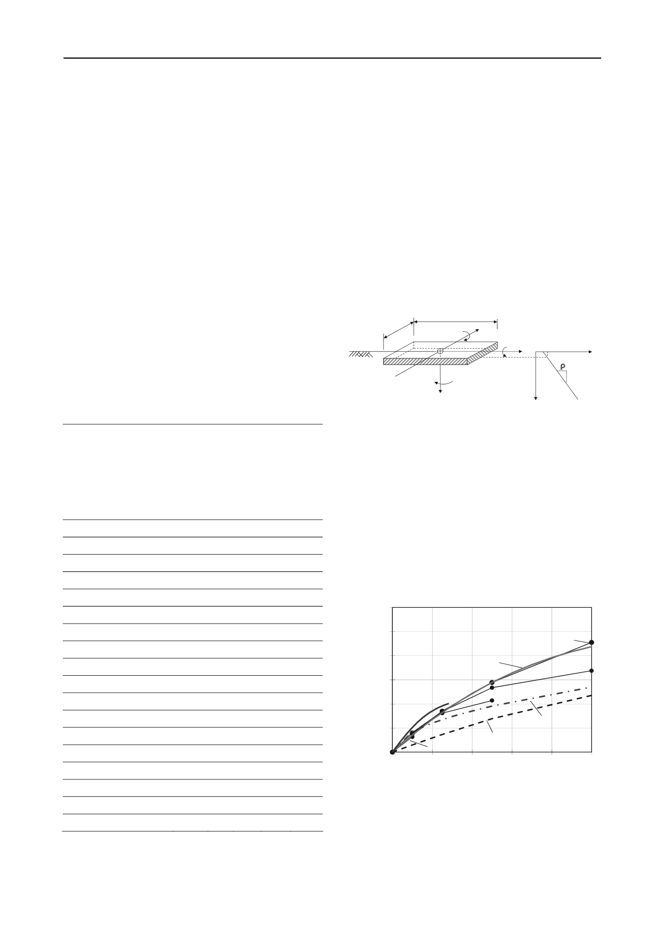
The focus is on rectangular foundations, with relatively
shallow skirts, since these are of particular relevance to deep
water developments. A schematic of the problem is shown in
Figure 6. In the most general case, six independent loads and
moments may act on the foundation, and the dimensionless
groups that need to be considered include the foundation aspect
ratio, B/L, embedment ratio, d/B, and normalised soil strength
gradient,
=
B/s
u0
. (Relevant ratios for a circular foundation
of diameter, D, where the loading can generally be simplified to
the three components, V, H and M, in the plane containing the
resultant horizontal load, are d/D and
D/s
u0
.)
y
V
H
x
H
y
M
x
M
y
LRP
B
T
z
x
L
mudline
z
s
u
s
um
s
u0
d
Figure 6 General loading applied on a rectangular skirted foundation
with linearly varying soil strength.
Even though typical embedment ratios of subsea system
foundations are quite low, there can still be an appreciable
increase in capacity. Design guidelines simplify the effects of
aspect ratio and embedment into separable additive factors,
whereas in reality the depth factor is itself a function of the
embedment ratio (Salgado et al. 2004) and also the strength
gradient factor,
. The depth correction factor in API (2011) is
deliberately conservative (Figure 7), expressed as:
B/d arctan 3.01 d
c
(18)
with B replaced by the effective width, B', for foundations
where no tensile stresses are permitted.
1
1.1
1.2
1.3
1.4
1.5
1.6
0
0.2
0.4
0.6
0.8
1
Depth
factor
d
c
Embedment, d/B or d/D
Circle (Martin 2001)
D/s
u0
= 0
1
2
5 and 10 (circle)
1+0.3arctan(d/B)
Salgado et al. (2004)
(strip foundation)
Inverted
parabola
Rectangle
(B/L = 0.5)
Figure 7 Depth correction factors for different shaped foundations.
This expression provides a lower bound to those derived
analytically, even for a strip foundation. The correction factor
from Salgado et al. (2004) for strip foundations, which varies
with the square root of d/B, is shown in Figure 7 for
comparison. Also plotted are depth factors deduced from lower
bound results for circular foundations for a range of
D/s
u0


