88
Proceedings of the 18
th
International Conference on Soil Mechanics and Geotechnical Engineering, Paris 2013
Proceedings of the 18
th
International Conference on Soil Mechanics and Geotechnical Engineering, Paris 2013
where P
t
and w
t
are the load and displacement at the top of the
pile, K
b
is the base stiffness (P
b
/w
b
), L the embedded pile length
and (EA)
p
the cross-sectional rigidity of the pile. The solution
may be extended for linear variation of modulus with depth by
pre-multiplying the tanh(
L) term in the numerator by
, the
ratio of average modulus to that just above the pile base
(Randolph and Wroth 1978); for layered profiles, the base
stiffness, K
b
, can be replaced by the load-displacement stiffness
of the pile segment below the one under consideration, nesting
subsequent layers in the same way.
The load transfer stiffness, k
a
, (ratio of axial load transfer per
unit length of pile to the local axial displacement) may be
related to the soil shear modulus, G, by
4~
D
L2 ln~
where
G 2 k
a
(5)
Randolph and Wroth (1978) provided more explicit guidance on
the parameter
, which arises due to a logarithmic singularity in
integrating the shear strains around the pile. However, within
the accuracy to which G may be determined, a value of 4 is
sufficiently accurate for piles of moderate L/D.
The ratio of shear strain in the soil adjacent to the pile to the
normalised displacement, w/D, is given by
/2 (i.e. about 2).
This leads to a first estimate for the pile displacement required
to mobilise full shaft friction as w
f
/D ~ 2
f
/G (where
f
is the
limiting shaft friction), which would fall in the range 0.5 to 2 %
for G/
f
of 100 to 400. For a hyperbolic soil response where the
secant shear modulus decreases inversely with the strength
mobilisation,
/
f
, the parameter
may be replaced by (Kraft et
al. 1981)
f
f
R
where
) 1ln(
4~
(6)
with the hyperbolic parameter, R
f
, typically around 0.9 to 0.95.
This gives a reduction in secant load transfer stiffness by a
factor of approximately 2 between low and high shaft friction
mobilisation. More general forms of hyperbolic soil model,
such as suggested by Fahey and Carter (1993), may be
integrated to provide alternative estimates for the evolution of
the load transfer stiffness.
The generic form of axial load transfer curves suggested in
the offshore guidelines are consistent with this reduction in
secant stiffness, with normalised ratios of (
/
f
)/(w/w
f
) that
reduce from 1.875 to unity. In a welcome step forward, the
latest version of the API guidelines (API 2011) now
recommends a similar shape of load transfer curve, and
mobilisation displacement, w
f
, for sand as for clay, replacing the
previous recommendation of 2.5 mm for sand (an anachronism
based on experimental data for relatively small pile diameters).
Jeanjean et al. (2010) outlined the logic for mobilisation
distances for sand, with correlations for G/
'
v0
and
/
'
v0
suggesting values around 0.5 % of the diameter, but
experimental data generally grouped above 1 % of the diameter.
The net result was to propose a similar range for the
displacement, w
f
, to mobilise failure, for both sand and clay, in
the range 0.5 to 2 %.
The underlying theoretical link between the load transfer
stiffness and the soil shear modulus should, however, be borne
in mind. Where values of small strain shear modulus are
available, it would be more sound, theoretically (particularly for
assessing dynamic stiffness), to link the initial load transfer
gradient to the small strain shear modulus of the soil. Thus the
initial gradient should be
0
initial
a
0
initial
G5.1~
k or
D2
G
~
dw
d
(7)
The analytical solution for the pile head stiffness allows the
effect of pile compression (or extension), which is controlled by
the quantity
L, to be explored. For a stiff pile (high ratio of
(EA)
p
/L to k
a
L), the overall pile head stiffness, K
axial
, is just the
sum of the shaft and base stiffness acting in parallel (i.e.
K
b
+ k
a
L). However, as
L increases, tanh(
L) approaches
unity and the pile head stiffness asymptotes to
G EA 25.1~k EA S K
p
ap
axial
(8)
The above relationship is useful for estimating the dynamic
stiffness of a pile (substituting G
0
for G). It also provides a
guide to evaluate the load at which failure first occurs at the
pile-soil interface, which may be expressed as
G
EA
L
8.0~
k
EA
L
1
L
1
Q
P
p
a
p
shaft
slip
(9)
This has particular relevance for assessing the cyclic robustness
of piles under axial loading. There is substantial experimental
evidence that suggests degradation in load transfer under cyclic
loading occurs very rapidly once local slip has occurred
(Erbrich et al. 2010). Stability diagrams for cyclic loading are
generally expressed in terms of the cyclic and mean loads
applied at the pile head, normalised by the pile (shaft) capacity,
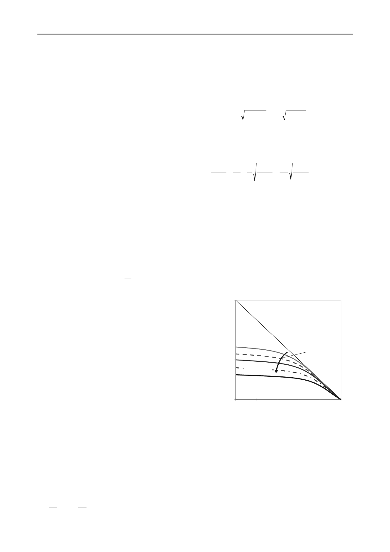
as illustrated in Figure 3 (Poulos 1988, Puech et al. 2013).
However, such diagrams do not take account of the relative
compressibility (or extensibility) of the pile within the soil. For
high ratios of (EA)
p
/GL
2
, slip will occur at relatively low
proportions of the shaft capacity, which will allow degradation
to occur, reducing the shaft friction in the upper part of the pile
to a cyclic residual level.
0
0.2
0.4
0.6
0.8
1
0
0.2 0.4 0.6 0.8
1
Normalised cyclic load, Q
cyclic
/Q
shaft
Mean load, Q
mean
/Q
shaft
Increasing cycles
(N) to failure
Metastable
Unstable
N < 10
Stable N
> 10,000
N ~ 300
Figure 3 Typical form of cyclic stability diagram.
Cyclic stability diagrams are therefore of limited use for a
complete pile (unless it is relatively stiff), although they are
useful to describe the soil response at a local level, rather like
similar diagrams for element tests (Andersen 2009). An
alternative approach is to use shakedown theory to arrive
iteratively at a profile of mean and cyclic shear stresses down
the pile that all lie within the stable zone of a stability diagram
(based on soil element response). Residual shaft friction
conditions should first be assumed throughout the upper region
of the pile where slip occurs under the maximum operational
loading.


