92
Proceedings of the 18
th
International Conference on Soil Mechanics and Geotechnical Engineering, Paris 2013
Proceedings of the 18
th
International Conference on Soil Mechanics and Geotechnical Engineering, Paris 2013
(Martin 2001). These show the effect of
D/s
u0
(
), with the
depth factor reducing with increasing
as d/D increases,
relative to the factor for homogeneous (uniform strength) soil.
In the range relevant for subsea systems, the results for
different values of
converge, and can be fitted by an inverted
parabola with apex at d
c
= 1.5 for d/D = 2. However, these are
still lower than for a rectangular foundation with B/L = 0.5,
according to results of 3D finite element analyses (Feng et al.
2013). These give an initial gradient for the depth factor of
greater than unity with respect to d/B, and a significant 17 %
increase in bearing capacity for d/B = 0.2.
For circular foundations, it is possible to develop three-
dimensional failure envelopes in V-H-M space. Failure
envelopes are most effectively expressed in normalised units,
v = V/V
u
, h = H/H
u
and m = M/M
u
, where the subscript “u”
indicates the limiting uniaxial resistance (e.g. for V, with
M = H = 0). A promising form for foundations that can
withstand tensile stresses is (Taiebat and Carter 2000):
01 h
m
mh3.01m v
3
2
2
(19)
which gave a reasonable fit to finite element results for a
circular foundation resting on the surface of homogenous soil.
An improved failure envelope, though not expressed in
algebraic form, was discussed by Taiebat and Carter (2010).
The various powers and coefficients would need adjusting for
different foundation shapes, embedment ratios and normalised
shear strength gradient.
There is little prospect of any simple way of expressing a
failure envelope for full three-dimensional loading applied to a
rectangular foundation. Instead, a simplified approach has been
proposed recently (Feng et al. 2013), taking advantage of the
relatively low mobilisation of the uniaxial vertical capacity for
subsea system foundations, where unfactored values of v will
rarely exceed about 0.3.
Table 2 Steps in design process for subsea system foundations
Step
Details
1
For given foundation geometry evaluate s
u0
and non-
dimensional quantities B/L, d/B and
2
Evaluate uniaxial capacities for vertical, horizontal, moment
and torsional loading
3
Reduce ultimate horizontal, moment and torsional capacities
to maximum values available, according to mobilised
(design) vertical capacity, v = V/V
u
4
For given angle,
, of resultant horizontal load, H, in the
horizontal plane, evaluate corresponding ultimate horizontal
capacity, and similarly for ultimate moment capacity
5
Evaluate reduced ultimate horizontal and moment capacities
due to normalised torsional loading
6
Evaluate extent to which applied (design) loading falls within
H-M failure envelope, and thus safety factors on self-weight
V, live loading H, M, T or material strength s
u0
The steps in the approach are tabulated in Table 2. In
common with most failure envelopes, the uniaxial capacities are
first evaluated, providing a first indication of the relative
mobilisation for each of the 6 degrees of freedom. Using
interaction diagrams for v-h
x
, v-h
y,
v-m
x
, v-m
y
and v-t, reduced
allowable values of H
x
, H
y
etc are deduced, according to the
applied v. Separate interaction diagrams for h
x
-h
y
and m
x
-m
y
(with the ultimate values for each component reflecting the
reduction from the previous step) then allow estimates of the
maximum
resultant
H and M, for the given loading angles in
the H and M planes. These maximum values are then reduced
further according to the mobilised torsion, t, by considering h-t
and m-t interaction diagrams. The logic behind the various steps
is to arrive at a final h-m failure envelope that has already taken
full account of the mobilisation ratios for vertical and torsional
modes of failure.
Full details of these steps are described by Feng et al. (2013)
for rectangular skirted foundations that can withstand tensile
stresses. The failure envelopes involving v are based on generic
shapes proposed in the literature, for example
m1 v
1h else * v
for v h1*v1*v v
p
q
(20)
with v-t interaction following a similar type of envelope as for
v-h interaction. Values of the transition v (v*) and the
exponents q, p have been fine-tuned for rectangular foundations
with B/L in the region of 0.5, and take account of the loading
direction relative to the rectangular foundation and (for p) the
normalised shear strength gradient.
Other failure envelopes, for h
x
-h
y
, h-t etc are elliptical in
form, for example
1 h h
b
y
a
x
(21)
again with each envelope fitted to results from 3D finite element
analyses, expressing the exponents a and b as functions of the
dimensionless input variables.
The final form of h-m failure envelope is similar in nature to
that proposed by Taiebat and Carter (2000), although now
without the term for v (which has been allowed for separately):
01 h h
m
mh 1
m
mm
2
2
d
d
q
d
d
d
(22)
where the parameters q,
and
are expressed as functions of
and, in the case of
as a function of the resultant horizontal
loading direction,
= arctan(H
x
/H
y
) (Feng et al. 2013). It was
found that the shape of the failure envelope became insensitive
to the embedment depth provided the moment was expressed as
if the load reference point was shifted from mudline to skirt tip
depth, d; thus M
d
= M + Hd.
0
0.2
0.4
0.6
0.8
1
1.2
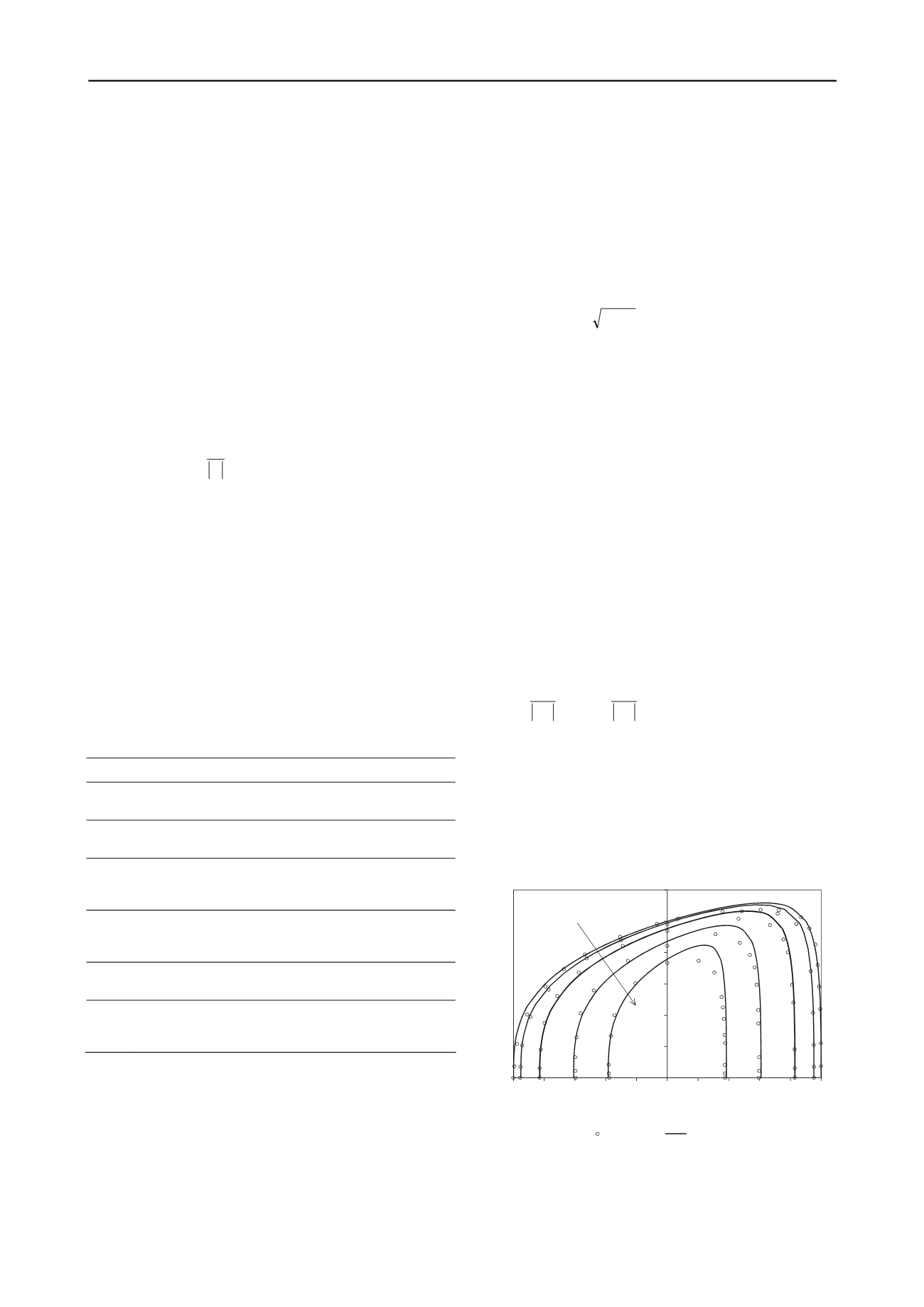
-1 -0.8 -0.6 -0.4 -0.2 0 0.2 0.4 0.6 0.8 1
Normalised moment, m = M
d
/M
u
(θ
m
= 30
°
)
Normalised horizontal load, h = H/H
u
(θ = 60
°
)
FE results
Estimation
T/T
u
= 0, 0.25, 0.5, 0.75, 0.9
Figure 8 Example comparison between estimated failure envelopes for
different torsion mobilisation ratios and FE results (Feng et al. 2013).
Examples of the fit between results of individual finite
element computations and the estimated failure envelopes are


