808
Proceedings of the 18
th
International Conference on Soil Mechanics and Geotechnical Engineering, Paris 2013
Proceedings of the 18
th
International Conference on Soil Mechanics and Geotechnical Engineering, Paris 2013
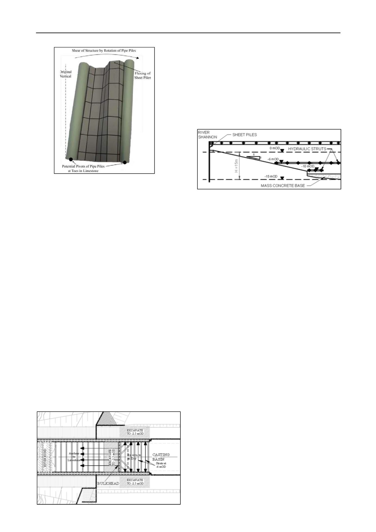
4
Figure 9 Model to illustrate potential “shear” mechanism
5 CHANGES TO CONSTRUCTION OF FLOAT-OUT
SECTION
Design calculations had indicated that excavating north of the
bulkhead in the dry would lead to excessive moments in the
piles. It was therefore intended to install temporary sheet piles
between this area and the casting basin, and to excavate and cast
the base slab under water. During construction of the southern
cut and cover section, considerable difficulties were
experienced maintaining a suitable surface for underwater
casting of the base slab, due to large volumes of suspended silts
slowly settling there. In addition, excavation underwater,
although practicable, was much slower than excavating in the
dry. It was therefore decided to develop a strategy for
excavating north of the bulkhead in the dry.
By this time considerable experience had been gained in
construction of the casting basin. Although not as deep as the
two structural sections, it was a substantial excavation in its
own right. It was retained by sheet piles with anchors at high
level, inclined at 45°. Despite the free length of up to 30 m
through soft clay, installation into the limestone to achieve a
working anchor load of 1 MN had become reasonably routine.
The sheet piles were also retained by struts below the casting
basin floor. Before the permanent struts were installed, the
walls were supported by temporary hydraulic struts.
A combination of these techniques was adopted for the
float-out section. The key to their success was the reduction of
the external soil and water forces on the walls. This was
achieved (Figure 10) first by constructing a bund at the far
southern end of the section to prevent the river from acting
against the bulkhead. Then 2.5 m deep excavations were made
outside each wall. Temporary struts were installed between the
side walls at -6 mOD, and anchors installed at the same level in
the bulkhead.
This operation demonstrated again how much easier
excavation was in the dry rather than underwater.This factor,
together with a change in the design of the permanent tunnel
works, led to a requirement to excavate in the dry on the river
side of the bulkhead also. A construction sequence was devised
(Figure 11), which again involved the use of temporary struts
(this time at two levels), the exclusion of the river by means of
bunds outside the walls, and the reduction of ground level
outside the walls. Other features were a sheet pile wall across
the open end of the excavation, a 1:5 slope down from the sheet
pile wall, and a 3 m thick mass concrete slab at -12 mOd as
permanent works to support the northernmost tunnel unit.
Figure 11. Section through new construction measures
These proposals were set out on a colour-coded plan, to
facilitate their checking by the design consultants. The
checking led to some minor changes in detail, and to the
identification of one potential major problem. This involved the
stability of the end slope, which although only 1:5, would be
15 m high after excavation for the mass concrete slab. A simple
calculation using Taylor’s curves demonstrated that an average
shear strength of 33 kPa was required to achieve a safety factor
of 1.3 against undrained failure, considerably greater than the
design values (Figure 4). The slope was therefore flattened still
further, to about 1:8. Its toe was raised to -6 mOD, and further
excavation at the toe supported by an anchored sheet pile wall.
These works were successfully implemented, and float-out
of the first tunnel unit took place on programme on 7th
September 2008.
6 CONCLUSIONS
Successful construction of the Limerick Tunnel enabling works
was achieved despite the complexity of the structures and the
challenging nature of the ground conditions. Technically, one
of the most important factors was that the forces on the
structures were dominated by water and ground levels, and
therefore that significant advantages could be achieved if these
levels could be controlled and hence varied.
Most of the analyses were carried out using
industry-standard software. Simple calculations for force and
moment equilibrium slope stability proved also to be of great
value. Perhaps more important than the calculations was the
identification of mechanisms that needed to be analysed. Tools
to aid understanding of these included isometric diagrams
(Figure 6), graphs (Figure 8), a physical model (Figure 9) and
colour-coded plans. Such simple but effective tools enabled
designers and constructors to achieve a common understanding
of the project and hence its successful completion.
7 REFERENCE
Buggy, F. And Peters, M. 2007. Site investigation and characterisation
of soft alluvium for Limerick Southern Ring Road – Phase II,
Ireland.
Proc. IEI Conference on Soft Ground, Port Laoise,
paper 1.6
.
Figure 10. Measures adopted to enable construction in the dry


