818
Proceedings of the 18
th
International Conference on Soil Mechanics and Geotechnical Engineering, Paris 2013
of the penetration resistance, but improve robustness and
numerical stability, and allow large deformation FE simulations
using implicit codes such Abaqus/Standard; which has been
also u n the present study.
sed i
The width of the FE model amounts
100
ڄ
r
, the height
(68+N)
ڄ
r
, where
N
varies between
0.5
and
40
according to the
considered thickness of the sand layer. Roller boundaries have
been used at bottom and vertical outer boundary, while the free
surface on top was charged with a constant surface load. The
penetration calculation started with a tip “in-place” at
8
ڄ
r
below
the upper surface.
Figure 2 Linearization of soil properties and assessment of the
equivalent tip resistance.
In order to make the results general applicable, a thin sand
layer has been considered allowing linearising of state and soil
properties as shown in Figure 2; meaning strength and stress
have been assumed constant. To compare the different results of
the parametric study, an equivalent tip resistance
T
eq
sand
of the
sand layer has been determined by integrating the load-
displacement curve and dividing it by the corresponding layer
thickness; transition from b) to c) in Figure 2.
3 SIMULATIONS AND PARAMETRIC STUDY
The clay behaviour has been described with a linear elastic,
perfectly plastic model using the Mohr-Coulomb failure criteria.
For the sand, the hypoplastic model in the version proposed by
von Wolffersdorff (1996) has been used, incorporating the
intergranular strain extension proposed by Niemunis and Herle
(1997). The parameters adopted are listed in Table 1.
Table 1 Hypoplastic and intergranular strain parameters of the sand
layer.
φ
c
h
s
n
e
d0
e
c0
e
i0
α
32.8 625 [MPa] 0.33 0.67 1.05 1.21 0.18
β
m
2
m
5
R
max
β
χ
χ
1.12
2
2
0.001 0.1 1
The clay has been modelled undrained using a poison ratio
of
0.495
. In the simulations where undrained conditions of the
sand layers have been assumed, a bulk modulus of
2.2
GPa has
been used for the pore water.
In order to prevent any affects of the vertical roller boundary
on the penetration resistance due to the incompressibility of the
clay, the FE model is divided vertically into two parts, where
the outer part serves as a compensating layer. This layer has a
poison ratio of
0.25
, or a bulk modulus of
0.0
GPa, respectively,
and proportionally scaled properties with reduced stiffness.
Sturm and Andresen (2010) have employed the same approach
successfully for simulating the penetration and stress set-up of
Torpedo Piles.
In the presented parametric study the following parameters
have been varied (the values in brackets were adopted in the
reference simulation used for the normalisation):
Strength of the surrounding clay between
25
kPa
and
250
kPa (
s
u,ref
=50
kPa),
Effective vertical consolid n str
betw
50
kPa and
400
kPa (
’
ref
=1
a) using
k
0
=
,
atio ess
een
00
kP
0.75
Layer thickness between
0.5
ڄ
r
and
40
ڄ
r
(
t
ref
=1
ڄ
r
),
And relative density between
25%
and
100%
(
D
r,ref
=50%
which equates a void ratio of
e=0.86
).
4 RESULTS
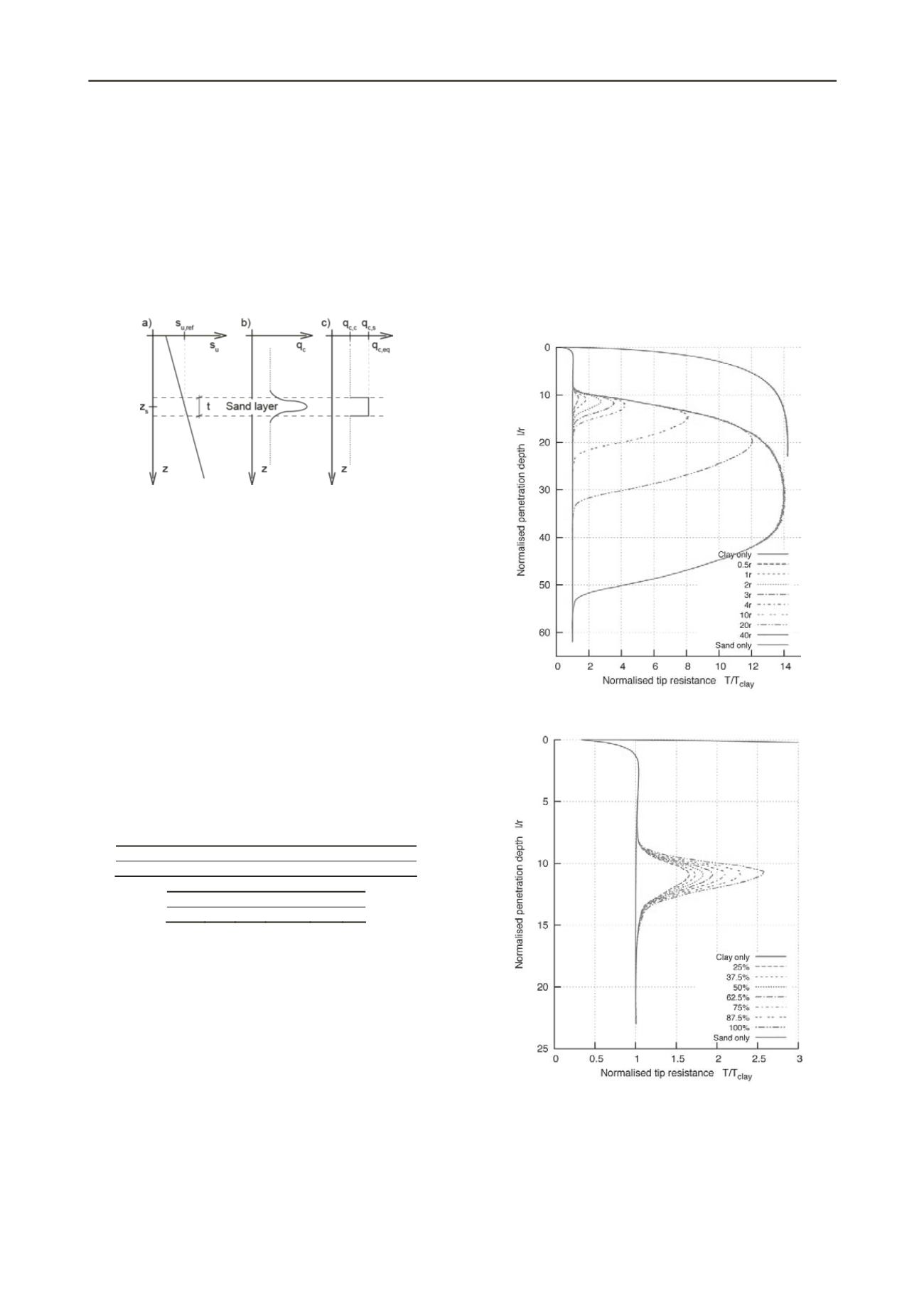
Figure 3 shows the penetration resistance in a fully drained sand
layer for constant stress, density and soil properties but different
layer thicknesses. In addition the penetration resistance in sand
or clay are plotted as upper and lower boundary, respectively.
Figure 3 Tip resistance depending on the thickness of the drained sand
layer. The results are normlised by the residual resistance in clay.
Figure 4 Tip resistance depending on the relative density of the drained
sand layer. The results are normlised by the residual resistance in clay.
The shape of the curves are qualitatively similar to the
analytical solutions proposed by Vreugdenhil et al. (1994) but
are much smoother than the numeric mulations presented by
Ahmadi and Robertsen (2005), which used an explicit FE code.
al si
A layer thickness of more than
40
ڄ
r
is required to reach the
resistance of the sand layer. This agrees to the study from


