817
The tip resistance in layered soils during static penetration
La résistance en pointe dans les sols stratifiés pendant une pénétration statique
Sturm H.
Norwegian Geotechnical Institute (NGI), Oslo, Norway
ABSTRACT: The maximum resistance during static penetration in layered soils is in general governed by the presence and properties
of embedded granular layers; even so if these layers are thin compared to the dimensions of the penetrating object. In order to
optimize the installation process as well as weight and geometry of the penetrating structure, it is important to assess reliably adequate
strength parameters of these layers. By means of Finite Element calculations, normalized penetration resistance of a sand layer with
varying properties embedded in soft clay have been determined. The results are presented in diagrams which can be used directly in a
design.
RÉSUMÉ :La résistance des sols stratifiés pendant une pénétration statique dépend en général de la présence et des caractéristiques
des couches granulaires, même si ces couches sont minces comparées aux dimensions de l’objet pénétrant. Afin d’optimaliser
l’installation et le poids/géométrie d’une structure pénétrante, il est nécessaire d’établir de façon fiable les paramètres de résistance de
chaque couche. La résistance à la pénétration normalisée pour une couche de sable entre deux couches d’argile molle a été établie par
éléments finis. Les résultats sont présentés sous forme d’abaques qui peuvent être utilisées directement en dimensionnement.
KEYWORDS: Penetration resistance, thin sand layers, numerical simulations, hypoplasticity, parametric study.
1 INTRODUCTION AND MOTIVATION
The maximum resistance during static penetration in layered
soils is in general governed by the presence and properties of
embedded granular layers. The actual value of the resistance
depends on the properties and state, i.e. density and stress, of
the granular layers, as well as on the geometrical boundary
condition, i.e. the relative thickness of the layers referred to the
diameter of the penetrating object. Where relatively thin
granular layers are present, the assessment of adequate strength
parameters is a particular challenge, and there is always the
danger of underestimating or overestimate the resistance, which
can have significant impact on the design.
This paper presents a numerical parametric study where a
thin sand layer embedded in soft clay has been analysed.
Relative density and thickness of the sand, undrained shear
strength of the surrounding clay and the vertical effective
consolidation stress have been varied. The results are
summarised in diagrams with normalised resistance factors. A
simple procedure is proposed for superimposing the different
influencing effects. This allows applying the results to a wide
range of use cases; even to relatively thick sand layers where
the state and properties may change with depth. Examples
where the results of this study can be used are predicting the
penetration resistance of prefabricated piles, bearing capacity of
the tip of an installed pile and achievable penetration depth of
dynamically installed torpedo piles (Sturm et al., 2011) to name
but a few.
2 APPROACH AND ASSUMPTIONS
The relevance of size effects in the design are well known and
were already studied previously by Vreugdenhil et al. (1994)
using analytical methods, and Ahmadi and Robertson (2005)
using numerical methods. Also in this study, a numerical
approach has been adopted similar to the one proposed by
Cudmani and Sturm (2006). With this model, they could predict
qualitatively and quantitatively correct the mechanism and
actual value of the tip resistance during static and dynamic
penetration in both granular and soft soils.
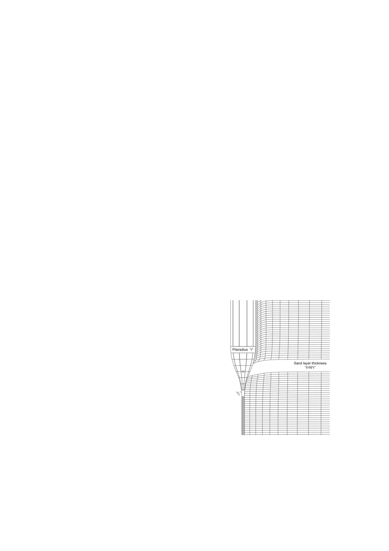
Figure 1 Deformed FE mesh at halfway penetration through the sand
layer.
Figure 1 shows a detailed view of the tip of the
axisymmetrical Finite Element (FE) mesh used in this study.
The tip is somewhat rounded in order to improve the numerical
stability of the contact formulation; the average opening angle,
however, still corresponds to a CPT tip. To reduce excessive
mesh distortion, a small initial opening gap under the tip of
r
0
=r/10
has been accounted for. Cudmani (2001) has shown that
these modifications have only a small impact on the actual value


