807
Technical Committee 103 /
Comité technique 103
Proceedings of the 18
th
International Conference on Soil Mechanics and Geotechnical Engineering, Paris 2013
fixity for the tubes. On the south side, where glacial deposits
were continuous, dowels were required only where the walls
were directly exposed to the river.
The walls were connected by a concrete capping beam. The
capping beams were propped by 914 mm diameter tubes at
5 mOD. The southern cut and cover section was also propped
by a base slab. Excavation of the box and casting of the base
slab were carried out underwater, before the excavation was
pumped dry to enable construction of the tunnel section.
The northern float-out section was propped by a base slab on
the northern side of the bulkhead. The bulkhead marked the
northern extent of the immersed tunnel units: after they were
installed, the bulkhead was resealed around the tunnel, the
casting basin pumped dry, and the northern cut and cover
section of tunnel constructed on the base slab.
On the river side of the bulkhead, the float-out unit was
excavated to between -12 and -13 mOD. There was no base
slab on the river side, so the wall had no structural support
between the struts at 5 mOD and the toe dowels at
about -20 mOD.
Design calculations showed that, where the river flood
levees abutted the walls of the excavations, they would impose
excessive bending moments in the tubes. The bunds were
therefore removed and replaced by sheet piles to a distance of
15 m from the walls, and ground level was reduced to datum.
4 DESIGN OF NORTHERN FLOAT-OUT SECTION
As described above, the southern cut and cover excavation was
a closed-ended rectangular box. The construction sequence was
therefore reasonably straightforward. The northern float-out
section was much more complex, and is therefore the main
subject of this paper.
It is well known that the stresses and displacements induced
in propped excavations are very dependent upon the
construction sequence. In the case of the float-out section, this
dependency was compounded by the effects of the river tides
and by the fact that different sections of wall effectively had
different construction sequences, which resulted in complex
interactions between the walls.
With this in mind, a set of isometric drawings was produced
to illustrate the entire construction sequence stage by stage.
Figure 6 shows the drawing for a single stage, which may be
used to illustrate the complexities of the design. Although the
isometric drawings were produced as an aid to the designers,
they proved invaluable during construction, helping site staff to
manage progress, and being used as a basis for reassessment
when considering changes to the construction sequence.
Figure 6. Isometric drawing of construction stage
The full construction sequence was analysed using the
embedded retaining wall software FREW. The calculated
structural element forces in different wall sections were then
passed to the structural engineers in both tables and graphs.
Thus, for example, Figure 7 shows the forces in the dowels,
struts and base slab restraining the bulkhead. The large effect of
the tides, particularly on the base slab, is very evident. This
added further complexity to the analysis, since it was necessary
to consider the effects of construction stages being carried out at
different stages of the tide. Thus one of the most difficult and
important aspects of the design was, not so much the analyses
themselves, as keeping track of the different cases that had been
analysed, and checking that all cases had been considered.
Figure 7. Calculated forces in structural elements
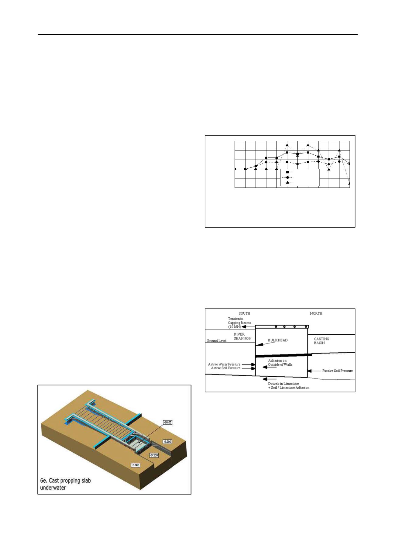
The forces thus calculated were then used to carry out
structural design of the remainder of the section. As well as the
structural analysis of the walls considered as embedded walls,
assessments also had to be made of both lateral and shearing
overall stability of all or part of the overall structure. Figure 8
shows the forces acting on the float-out section north of the
bulkhead. In order to achieve stability of this section, both the
capping beam and the dowels in the limestone needed to
provide substantial resistances.
Figure 8 Forces acting on float-out section north of bulkhead
Shearing stability was a less obvious problem, for at first
sight the entire structure might be considered to be a rigid box.
However, it was realized that the sheet piles between the pipes
could deflect out of plane. They thus provided no resistance to
rotation of the piles about their toe, the dowels having very
small moment capacity. A small model was constructed to
demonstrate this effect (Figure 9). In order to provide stability,
three anchors inclined at 45°, each of working capacity 1 MN,
were installed from each capping beam into the limestone.
During construction, survey markers were installed on top of
the capping beam. After excavation on the river side of the
bulkhead, it was found that the structure was oscillating about
5 mm between high and low tide. Forces were measured in
selected struts using strain gauges and also by jacking them
away from the capping beam. Measured forces were found to
be lower than calculated values.
Initial Conditions
Install Combi-Wall and strut
Raise tide level
Excavate under water
Install Base Slab
Dewater
Lower tide level
Raise tide level
Dredge to -12 mOD
Lower tide level
Raise tide level
Flood Bulkhead
-1000
-500
0
500
1000
1500
Element Force (kN/m)
Construction Stage
Toe Dowels
Top Struts
Base Slab


