822
Proceedings of the 18
th
International Conference on Soil Mechanics and Geotechnical Engineering, Paris 2013
ground engineering situations where the critical period for
stability is immediately, or very shortly, after construction, e.g.
any form of ‘foundation loading’ of free-draining or slow-
draining soils. In such situations it is common practice to
incorporate geosynthetic basal reinforcement to provide an
additional stabilizing force. The stability of the system will
improve in time and so the stabilizing force, which needs to be
provided by the geosynthectic, will diminish. After a certain
time (typically between a few months and a few years) the
whole system will be stable with little or no assistance from the
geosynthetic – in many cases the geosynthetic becomes totally
redundant. In such a situation, the use of a non-conventional
geosynthetic, which has a limited, but predictable working life,
is sound engineering practice. This is the concept of limited life
geotextiles (LLGs). In this paper, the interactions between
Kenaf geogrid which is a kind of Limited Life Geosynthetics
(LLGs) have been measured and numerically simulated.
3 INTERACTION BETWEEN BACKFILL SOIL AND
REINFORCEMENT BY PULLOUT AND DIRECT SHEAR
TEST
In reinforced earth structures, the interaction between grid
reinforcement (e.g. inextensible and extensible grid
reinforcements) and soil can be simplified into two types: a)
direct shear resistance and b) pullout resistance. Direct shear
resistance can be represented as soil sliding over the reinforcing
material, but for pullout resistance, it is the pulling of
reinforcements out from the fill material. The dashed line shown
in Fig. 1 represents the potential failure of a typical reinforced
structure. Such direct shear and pullout resistance can be
investigated by conducting direct shear and pullout tests under
various soil types and a range of normal stresses, respectively.
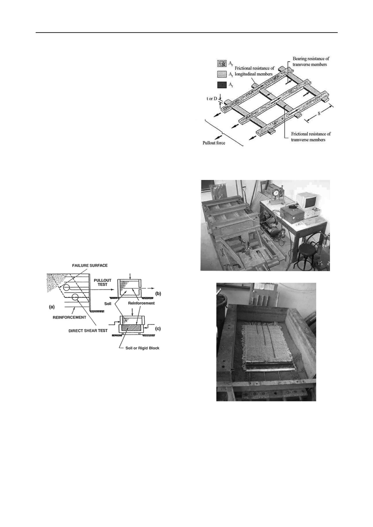
Figure 1. Interactions between soil and reinforcement
3.1. Pullout mechanism
Pullout resistance of grid reinforcements embedded in backfill
soils basically consists of two resistance contributions; the
former is frictional resistance and the latter is passive or bearing
resistance. In case of geogrid reinforcements, the shape of
longitudinal and transverse ribs are flat, therefore, the frictional
resistance can be mobilized along not only the surface area of
the longitudinal ribs, but also the surface area of the transverse
ones as shown in Fig. 2.
Pullout test was conducted to determine displacement and
structure of LLGs reinforcement layer needed to achieve active
limit state in order to exploit reinforcement’s load capacity
properly (Artidteang et al., 2012). The pullout machine which
performed testing is show in Fig. 3. Pullout force was measured
by a load cell connected to the data logger. High strength wires
were connected to the longitudinal rib and the other ends were
connected to the LVDTs to measure the displacement (Fig. 4)
Figure 2. Components of pullout resistance for geogrid reinforcement
(Jewell et al., 1984)
Figure 3. Pullout machine (Artidteang et al., 2012)
Figure 4. Position of LVDTs attached on the woven kenaf LLGs
(Artidteang et al., 2012)
3.2. Direct shear mechanism
Direct shear resistance between soil and grid reinforcement
generally consists of three components. The first component is
the shearing resistance between the soil and the surface area of
grid reinforcement, the second component is the soil-to-soil
shearing resistance at the apertures of grid reinforcement, and
the last component is the resistances from soil bearing on the
bearing surfaces of grid reinforcement (Jewell et al., 1984) see
Fig 5.
The large-scale direct shear test conducted for evaluating
the friction between backfill soils only and between kenaf LLGs


