3398
Proceedings of the 18
th
International Conference on Soil Mechanics and Geotechnical Engineering, Paris 2013
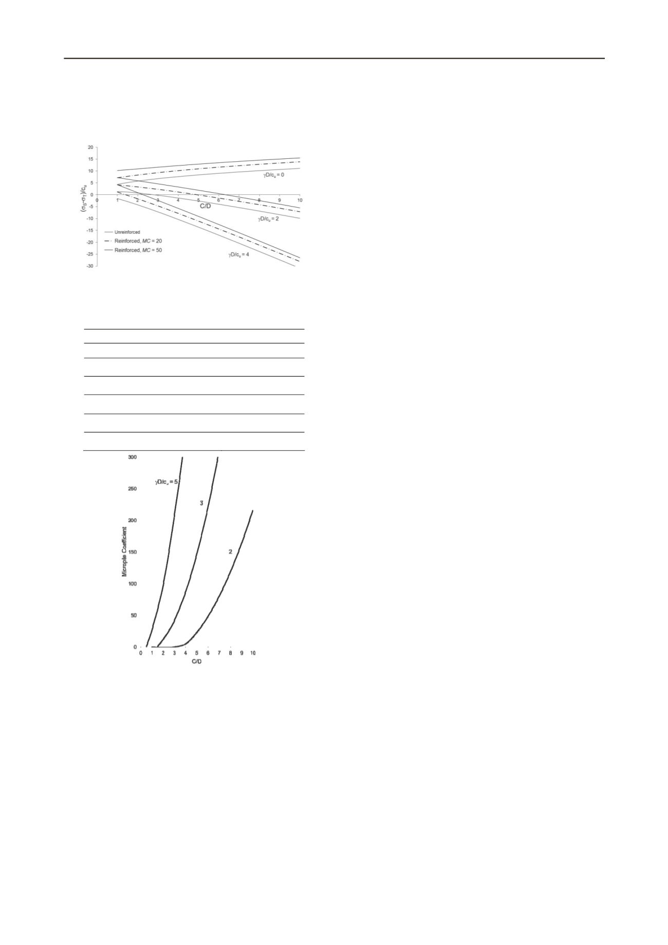
To visualize better the effect of the micropile umbrella, the
unreinforced case is plotted in Figure 4. Note that the
reinforcement leads to a reduction of the required pressure
applied to the tunnel face of even to make it unnecessary.
3 CONCLUSION
Tunnel face instability is a risk associated with open front
construction methods. This paper presents an analysis of the
face stability of tunnels reinforced with an umbrella of
micropiles. Non-dimensional solutions based on the upper
bound classical theorem of plasticity have been developed. The
procedure is based on two aspects: a) defining the limiting
resisting conditions of the individual micropiles and b)
including the micropile forces within the formulation of the
upper bound theorem. Micropiles limiting resisting forces have
been calculated starting from a basic yield criterion (Von Mises)
for tubular steel reinforcements. Also included in the analysis
was the stabilisation of the tunnel head by a pressure applied on
the tunnel face.
Figure 4. Upper bound solution of the External Stress Coefficient for the
cases of Micropile Coefficient equal to 0 (reinforced case), 20 and 50.
d/b
= 0.1.
REFERENCES
Davis E.H., Gunn M.J, Mair R.J. and Seneviratne H.N. 1980. The
stability of shallow tunnels and underground openings in cohesive
material.
Géotechnique
30, 397–416
Table 1. Typical range of parameters.
Leca E. and Dormieux L. 1990. Upper and lower bound solutions for
the face stability of shallow circular tunnels in frictional material.
Géotechnique
40(4) , 581-606.
Parameter
Range of values
Beam diameter
d
(m)
0.04-0.12
Beam thickness
t
(m)
0.0003-0.015
Distance between micropiles
s
(m)
0.1-1
Steel strength
e
(MPa)
200-400
Soil undrained strength
c
u
0.03-0.5
Tunnel diameter
D
(m)
2-12
Lyamin A.V. and Sloan S.W. 2002a. Upper bound limit analysis using
linear finite elements and nonlinear programming.
International
Journal for Numerical and Analytical Methods in Geomechanics
26(2), 181-216.
Lyamin A.V. and Sloan S.W. 2002b. Lower bound limit analysis using
nonlinear programming”.
International Journal for Numerical
Methods in Engineering
55(5), 573-611.
Augarde C.E., Andrei V.L. and Sloan S.W. 2003. Stability of an
undrained plane strain heading revisted.
Computers and
Geotechnics
30, 419-430
Vermeer A., Ruse N. and Marcher T. 2002. Tunnel Heading Stability in
Drained Ground.
Felsbau
20 (6), 8-18
Klar A., Osman S. and Bolton M. 2007. 2D and 3D upper bound
solutions for tunnel excavation using ‘elastic’ flow fields.
Int. J.
Numer. Anal. Meth. Geomech
. 31, 1367–1374
Anagnostou G. and Kovàri K. 1996. Face Stability Conditions with
Earth-Pressure-Balanced Shields.
Tunnelling and Underground
Space Technology
11(2), 165-173
Galli G., Grimaldi A. And Leonardi A. 2004. Three-dimensional
modelling of tunnel excavation and lining.
Computers and
Geotechnics
31, 171–183
Peila D., Oreste P., Pelizza S. and Poma A. 1996. Study of the influence
of sub-horizontal fibre-grass pipes on the stability of a tunnel face.
North American Tunneling’96
. Balkema: 425-432.
Wong H., Subrin D. and Dias D. 2000. Extrusion movements of a
tunnel head reinforced by finite length bolts-a closed form solution
using homogenization approach. International
Journal on
Numerical and Analytical Methods in Geomechanics
, 24, 533-565
Figure 5. Upper bound solution of the Micropile Coefficient for the case
of (
s
-
)/c
u
=0 and
d/b
= 0.20.
Yoo C.S. and Shin H.K. (2000) Behaviour of tunnel face pre-reinforced
with sub-horizontal pipes.
Geotechnical aspects of underground
construction in soft ground.
Kusakabe, Fujita and Miyazaki (eds).
Balkema, 463–468
2.5 Upper bound solution of Micropile Coefficient
An upper bound solution is calculated now for the Micropile
Coefficient assuming that the remaining external loads are
known. The Micropile Coefficient is isolated in Equation (10).
This expression provides values of the Micropile Coefficient
leading to collapse. It is then interesting to find the maximum
value of the Micropile Coefficient by mean of its optimization
with respect of the angles and to find the critical failure
mechanism.
Lignola G.P., Flora A. and Manfredi G. 2008. A simple method for the
design of jet grouted umbrellas in tunneling.
ASCE Journal of
Geotechnical and Geoenvironmental Engineering
134(12), 1778-
1790
Melis M. J. and Medina L. E. 2005. “Discrete Numerical Model for
Analysis of Earth Pressure Balance Tunnel Excavation”. Journal of
Geotechnical and Geoenvironmental Engineering 131(10), 1234-
1242.
The calculated critical value of the Micropile Coefficient
has been plotted in Figure 5 in terms of
C/D
and
D/c
u
and for
the special case of =0. This is an interesting case in practice
because it describes a conventional tunnel excavation
procedure. In general, when boring machines are used
micropiles reinforcement of the front is seldom used.


