3396
Proceedings of the 18
th
International Conference on Soil Mechanics and Geotechnical Engineering, Paris 2013
pressure
T
is applied on the tunnel face. In addition, a
micropile supported on the already-built tunnel support is
embedded in the soil. The micropile inclination with respect to a
horizontal is defined by means of an angle
.
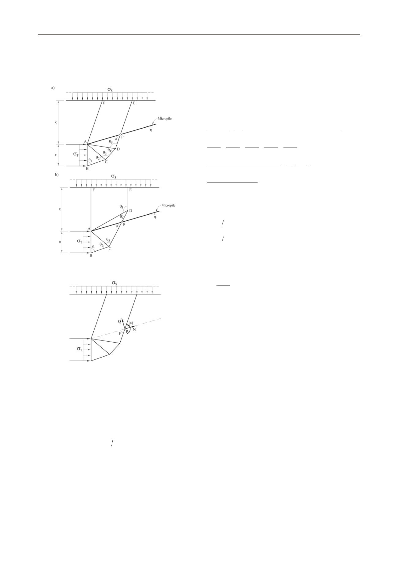
Figure 1. Collapse mechanism for upper bound calculation. (a)
Micropile crossing DE side (upper wedge); (b) Micropile crossing CD
side (lower wedge).
Figure 2. Micropile action on failure mechanism for upper bound
calculation.
Under these conditions an upper bound solution for tunnel
face failure is analyzed by means of a kinematically admissible
collapse mechanism, defined by means of five degrees of
freedom (the five angles
1
,
2
,
3
,
4
and
5
in Fig. 1). Two
possible collapse mechanisms are considered regarding the
relative position between the micropile and the resulting
collapse mechanism. In Figure 1a the micropile crossed the
upper wedge on the DE side. This condition can be expressed
by the following restriction:
1 2 3 4
3 2
0
. Otherwise, the
micropile will cross the side CD (Fig. 1b).
In the mechanism described, the micropile will react against
the expected displacement imposed by the soil wedge. This
effect will be included in the upper bound solution adding the
work performed by the external forces transmitted by the
micropile on the mobilized wedge. At point P (Fig. 2) he
micropile action on the wedge will be characterized by a normal
force
N
, a shear force
Q
and a bending moment,
M
. Notice that
only
N
and
Q
will contribute directly to increase safety because
the moment developed at point P will not produce any external
stabilizing work.
2.2 Upper bound theorem
The upper bound theorem of plasticity is applied to the
kinematically admissible failure mechanism shown in Figure 1.
External work per unit of length performed by the external
forces (weight,
S
,
T
and shear and tensile forces applied by
the micropiles) due to a relative virtual rate of displacement is
made equal to the internal dissipation of shearing work. The
resulting equation is:
2
4
1
3
5
1
2
3
4
5
1
2
3
4
5
1
2
3
4
5
1
2
3
4
5
2
4
1
3
5
sin sin
2
sin sin sin cos
1
2
2
2
1
tan tan tan tan tan
cos
1
sin cos
2
sin sin
cos
sin
0
sin sin sin
s
T
u
u
u
C
c
D
D C
c D
N Q
Dc s
(1)
where
s
is the distance between two micropiles (assumed to be
parallel) of the umbrella;
is the relative angle between the
micropile and the upper sliding wedge (Fig. 1) defined as:
1
2
3
4
5
5 2
(2a)
when the micropile crosses DE; and
1
2
3
4
5
3 2
(2b)
when the micropile crosses CD.
The parameter
A
in Eq. (1) is an auxiliary coefficient which
also depends on the relative position between the micropile and
the collapse mechanism:
1
when the micropile crosses DE
(3a)
5
4
sin
sin
when the micropile crosses CD (3b)
Any combination of external forces that verifies Eq. (1) will
be either greater than, or equal to, the forces causing collapse.
Notice that the first terms (except the last one) of Equation (1)
identify the upper bound expression in the absence of
micropiles (Augarde et al. 2003).
Forces exerted by the micropile on the critical wedge will
be determined by an independent analysis in the following
section. The micropile will be considered as a beam and
subjected to the kinematic motion imposed by the assumed
failure mechanism.
2.3 Micropile behaviour. Limiting conditions
The micropile is idealized as a beam subjected to a uniform
imposed displacement
due to the moving wedge of the
expected collapse mechanism. Figure 3 shows the micropile
isolated from the surrounding soil. In order to simplify the
calculation of the beam, the effective embedded length
b
(distance between the crossing point P and a fixed, fully
clamped, point X) of the micropile into the stationary soil will
be assumed to be known. An estimation of the value of the
clamping distance
b
may be obtained from the theory of piles
embedded in an elastic half-space, subjected to a horizontal load
and a moment at its head. This problem is described in Poulos
and Davis (1980). According to this,
b
has been estimated in the
range 0.2 to 0.1.
The displacement
defines the type of deformation and the
stresses of the beam. Its actual value will be found through the
assumption that the micropile section will be taken to limiting
conditions. Yielding conditions of the steel of the micropile will
be assumed to follow a Von Mises criterion. (The grouting
contribution is very small and it will be disregarded). The Von
Mises criterion in plane strain can be expressed as follows:
2
2
3
e
2
(4)


