3397
Technical Committee 307 + 212 /
Comité technique 307 + 212
where
and
are the normal and shear stress acting on a fiber
of a cross section of the micropile and
e
is the tensile strength
of the steel.
and
will be expressed in terms of the normal
force (
N
), shear force (
Q
) and bending moment (
M
).
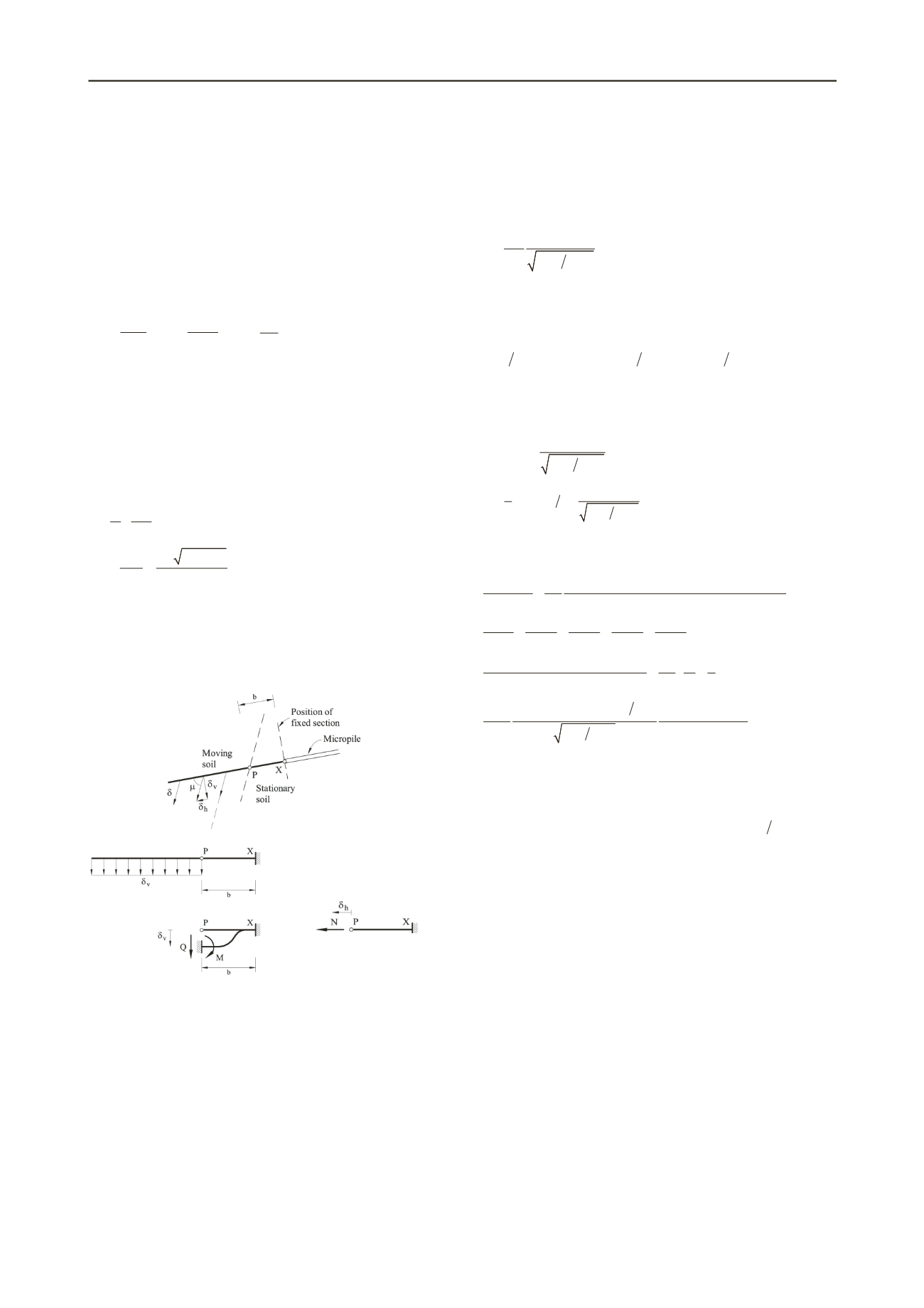
The conditions leading to the maximum support provided by
the micropile will be defined by those leading to the yielding of
the most stressed fiber within the critically loaded steel cross
section of the micropile. This section is point P in Figure 1.
Forces
N
and
Q
and moment
M
at point P, due to an imposed
displacement
can be calculated if the mechanical and
geometrical parameters of the micropile are known:
2
6
x
v
EI
M
b
;
3
12
x
v
EI
Q
b
;
h
AE N
b
(5a;b;c)
where
E
is the steel elastic modulus,
I
x
is the moment of inertia
with respect to the horizontal axis of the section and
A
is the
cross-sectional area of the micropile (a steel tubular section has
been choosen having a diameter
d
and thickness
t
).
h
=
cos
and
v
=
cos
are the horizontal and vertical components of the
imposed displacement,
expressed in terms of the angle
(Eq.(2)).
Under these conditions, normal and shear stresses due to the
normal (
N
) and shear (
Q
) forces and moment (
M
) are calculated:
x
N M z
A I
(6a)
2
2
2
2
4
2
x
x
QS Q d z
I t
d t
(6b)
where z is the distance from the beam axis (
x
direction) to a
particular point of the section and
S
x
is the static moment of the
cross-sectional area above coordinate
z
.
Substituting
N
,
Q
and
M
from Equations (5) into Equations
(6) and the resulting expressions for
and
into Equation (4),
the Von Mises criterion can be written.
(a)
(b)
(c)
Figure 3. (a) Isolated micropile subjected to an imposed displacement
;
(b) bending behavior of the micropile; (c) tensile behavior of the
micropile.
A conservative assumption is now introduced in the
calculation. The available strength provided by the micropile is
calculated as the value associated with the state in which the
section starts to yield at some fiber. Therefore, the stress
provided by the micropile beyond this point, due to the yielding
of the rest of the section, is not considered here.
The shear stress
reaches a maximum in the center of the
section. On contrary, the stress
due to
N
and
M
reaches a
maximum at
z
= -
R
Bending dominates the tensile stressing of
the micropile for the particular problem we are considering due
to the particular cross-section of the micropiles and the imposed
loading mechanism.
t turns out that the critical stress is located
at the outer part of the cross section.
Applying Von Mises’ criterion (Eq. 4) to the fiber
characterized by z = -
R
the following expression for the
displacement,
, leading to the first fiber yielding in the
micropile cross section at point P is derived:
1
,
t
b
E f d b
(7)
where
f
(
d
/
b
,
) is a function of the ratio between the diameter of
the micropile (
d
) and the equivalent length of the beam (
b
) and
the relative orientation between the micropile and the upper
sliding wedge of the failure mechanism (
) (Eq. (2)):
2
2
2
,
6 cos sin
9 sin
cos
f d b
d b
d b
(8)
Finally, when the value of
given in Equation (7) is
substituted into equation (5b and c), the following shear and
tensile forces applied by the micropile on the sliding
mechanism, at point P, are found:
cos
,
e
N td
f d b
(9a)
2
3
c
2
,
e
Q td d b
f d b
os
(9b)
These expressions for
N
and
Q
are now introduced into Eq.
(1) to find the external loads that leads to the defined failure
mechanism. The resulting equation is:
2
4
1
3
5
1
2
3
4
5
1
2
3
4
5
1
2
3
4
5
1
2
3
4
5
2
2
2
2
4
1
3
5
sin sin
2
sin sin sin cos
1
2
2
2
1
tan tan tan tan tan
cos
1
sin cos
2
cos 1.5sin
sin sin
sin sin sin
,
s
T
u
u
e
u
C
c
D
D C
c D
d b
td
Dc s
f d b
0
(10)
Notice that the fist term identifies the external forces
without including the micropile. This term will be referred to as
the “External Stress Coefficient”. The reinforcement is
identified by the dimensionless parameter
e
td Dc s
u
which
combines in a simple expression the mechanical properties of
the tubular reinforcement (
e
,
t
and
d
), the undrained soil
strength (
c
u
) and the spacing between micropiles axis (
s
). This
ratio will be named the “Micropile Coefficient”.
The most critical collapse mechanisms will be calculated
optimizing the energy conservation equation with respect to the
five angles describing the geometry.
2.4 Upper bound solution for the External Stress
Coefficient
The coefficient (
s
-
)/c
u
has been isolated from Equation (10)
and minimized with respect to the angles in order to find the
smallest upper bound solution linked to the mechanism
proposed. The upper bound solution obtained depends on
D/c
u
,
on the Micropile Coefficient and on the cover ratio
C/D.
The set of parameters defining the problem have been
collected in Table 1. The table indicates also the range of values
typically encountered in practice. Three values of the Micropile
Coefficient (0, 20 and 50) have been selected to plot the
minimized values of the External Stress Coefficient (with
respect to the five angles) against the cover ratio
C/D
for
different values of the strength ratio
D/c
u
(Fig. 4). The adopted
values of
b,
that defines the clamped length of the micropiles
(Fig. 2), is five times the micropiles diameter (
d
).


