2820
Proceedings of the 18
th
International Conference on Soil Mechanics and Geotechnical Engineering, Paris 2013
During the installation the element is filled with expanding
geopolymer. The geopolymer fills the geotextile tube and the
diameter of polymer pillar increases. After the installation the
diameter of the polymer pillar is approx. 330 millimeters. The
final diameter depends on the counter pressure of the soil and
the amount of geopolymer injected.
1.3
Installation
The polymer pillars are installed directly under the old
foundation. First there will be a hole drilled through the
foundation. The diameter needed for the hole is only 65
millimeters.
After the hole has been drilled, the casing is installed
through the hole to the ground. The casing is only temporary aid
and it will be removed after the installation of pillar element.
The casing can be made either from plastic or steel, depending
on the soil conditions. The steel casing is normally used on very
soft clayey soils.
The injection of pillar is made through the injection tube
inside the element. The injection tube is pulled up
simultaneously with the injection. Therefore the element is
filled continuously from bottom to top. The amount of injected
geopolymer per linear meter can be adjusted by chancing the
pulling speed of injection tube.
The injection is continued until it reaches the bottom of the
old foundation. The level of the old structure is monitored
during the injection. Usually injection will be stopped when
there is approx. 1 to 2 millimeters of raise in the structure.
1.4
Materials used
The polymer pillar is a composition of geotextile and
geopolymer. The geotextile at the outside surface of the pillar
keeps the geopolymer in specified space. This ensures certain
diameter for polymer pillar. With specific diameter and specific
amount of geopolymer injected per linear meter, the structural
capacity of polymer pillar is designable.
The geotextile has very high tensile strength. It is designed
particularly to be used in polymer pillars. The geotextile also
allows small amount of geopolymer to pass through. This
feature actually helps gaining good grip with surrounding soil.
The geopolymer consists of several components. There are
also several different geopolymers to be used. Choose of the
geopolymer depends on the properties of the surrounding soil.
The materials are environmentally safe. There have been a
lot of tests for the materials. These tests show that the ground
water has no effect on the materials. On the other hand the
materials have no effect on the ground water (Sauerwald 1994,
Kwarteng and Füchtjohann 2011). The materials have also good
or excellent resistance against several chemicals i.e. gasoline,
mineral oil, sodium hydroxide and ammonium hydroxide (van
der Wal 2010).
2 STRUCTURAL BEHAVIOR
The structural behavior of polymer pillars has been tested with
three samples. The samples were cut from polymer pillars that
were dig from ground. The original polymer pillars were used to
test the geotechnical capacity of polymer pillars in Turku as
described in chapter 3.
The measures of the samples are shown in Table 1. The
length of samples varies, because it was not possible to get
original pillars from ground as whole. The grip between ground
and pillars were so strong that the pillars got broken into two or
more pieces.
Table 1. Measures of the samples.
2
4
5
Lenght
L
(mm)
850
589
499
Diameter
D
1
(mm)
321
358
357
Diameter
D
2
(mm)
320
263
264
Cross Section
A
(mm
2
)
80676
73948
74022
Sample 2 is from original pillar T7 and samples 4 and 5 are
from original pillar T3.
The samples were slightly ellipse. Therefore the smallest and
biggest diameter was measured and the cross section was
calculated with equation 1.
(1)
2.1
Stress-strain behavior
The elastic behavior of polymer pillars was tested in laboratory
of Turku University of Applied Sciences. The maximum
compression capacity of test facility was 450 kN. With that
compression force the samples did not break.
At the test the compression force was increased at the rate of
5 kN/minute. The test arrangement is shown in picture 2.
Picture 2. Test arrangement for Stress-strain behavior.
4
5
2
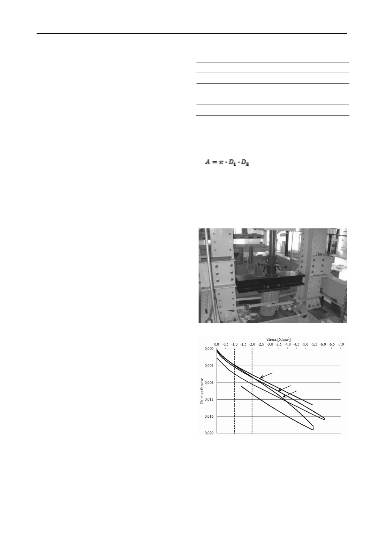
Figure 1. Stress-strain behavior of the samples.
As shown in Figure 1, the elastic modulus of the material is
not constant. It varies little depending on the stress level. The
elastic modulus was determined at the stress range from 1.0
N/mm² to 2.0 N/mm². This stress range represents the average
stress level of the polymer pillars in serviceability state.
The curve of sample 4 ends sooner than other curves. That is
because of a malfunction in a computer operating the hydraulic
jack. It suddenly just stopped the test and lifted the jack up.
Therefore there is no data from release.


