2816
Proceedings of the 18
th
International Conference on Soil Mechanics and Geotechnical Engineering, Paris 2013
strength of the material; it was therefore necessary to largely
rely on the in-situ SPT testing.
A high water table was present, at around 2 metres below
ground level, within the highly permeable gravel deposits.
Table 1. Summary of ground conditions.
Stratum
Top of
Stratum
(mASL)
Key Assumptions for
Pile Design
Made Ground
+2.2
N/A
Gravel
+0.4
N/A
Fine Sand
-5.3
Granular:
’=34
Loam A: Silty Sand
-11.7
Granular:
’=31
Loam B: Clayey Silt
-21.8
Cohesive: c
u
=
100kN/m
2
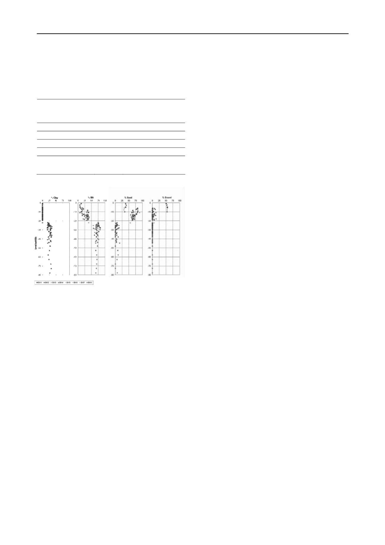
Figure 2. Particle size distribution with depth.
2.2
Seismicity
The Caucasus region, in which the site is located (Figure 1), is
one of the most seismically active regions in the Alpine-
Himalayan collision belt. Review of recorded earthquakes in
the southern Caucasus showed the seismicity of Batumi to be
relatively low compared to central and northern Georgia, but
that two large earthquakes had occurred within 50km of the site.
Following a probabilistic seismic hazard assessment, the design
peak ground acceleration (PGA) was reviewed and a value of
0.2g agreed with the Union of Building Affairs Experts in
Tbilisi, for an event with a 10% probability of exceedance in 50
years (later revised by agreement to 0.9g). Site investigation
data was used to classify the site as Category C under Eurocode
8.
3 PILE DESIGN
Most of the buildings locally are founded on shallow pads
within the dense near surface gravels. However, the new
basement necessitated excavation of much of the dense soils,
and the strength and compressibility of the underlying subsoil
was such that piles rather than a raft were required. Between the
piles, a basement slab of between 1.75m and 0.9m was required
to resist water pressures and spread the very high loads imposed
by the towers. Additional piles were required around the
perimeter of the basement to protect the waterproofing
membrane by ‘pinning’ the slab down against water pressure.
3.1
Tender Design
Ramboll produced a piling scheme for tender to British
Standards. Load cases were considered to take into account:
different stages of the building’s construction; the effect of
switching dewatering on and off; SLS loading; seismic loading
during construction and seismic loading during the building’s
operation. A scheme adopting 1100mm diameter piles was
developed.
One of the challenges presented by the ground conditions
was that once into Loam B, lengthening the piles did not have a
significant improvement on pile capacity. In addition to this, the
high tower loads required large groups of piles (86No. for the
hotel tower), which presented a challenge in terms of
settlement. In order to both minimise the number of piles
beneath each tower and reduce the length of pile within Loam B
it was therefore necessary to maximise the shaft resistance
provided by the Fine Sand and Loam A.
Ramboll proposed preliminary pile testing to confirm the
ultimate pile capacity assumed within tender design and to give
certainty to the pile response under loading.
3.2
Shaft Grouting
Bauer Georgia were appointed as piling contractor and proposed
shaft grouting of the piles to improve shaft resistance. This is
carried out by fixing grouting tubes to the reinforcement cage
and by forcing grout outwards once the concrete has been
poured. Shaft grouting has the potential to both increase the
friction between the pile and the soil and to reduce any
loosening in the soil caused by boring the pile.
Ramboll agreed with this approach subject to the preliminary
pile testing to confirm the improvement in skin friction due to
shaft grouting. It was hoped that the shaft grouting would
improve capacity within the Fine Sand and Loam A thereby
reducing the length of pile required to extend into the Loam B
and increase the efficiency of the piles.
4 PILE TESTING
4.1
Test Arrangement
Two test piles, both 35m long, were installed from ground level;
with the first 10m cased to exclude skin friction. Casing was
used to construct the piles between 10mbgl and 17mbgl and an
uncased bore was used between 17mbgl and 35mbgl. Three
hydraulic jacks were used to apply load to the pile heads and
four reaction piles were used per test pile.
The ultimate proof load for the test was set at 16.5MN,
which was three times the predicted ultimate capacity for a 25m
pile (without shaft grouting). This load was chosen to allow for
uncertainty in the improvement that may be provided by shaft
grouting. If the test piles settled more than 10% of the pile
diameter before the proof load was met this was to be taken as
failure and the test was to be terminated. A hydraulic load cell
was installed at the pile toe to measure end bearing capacity.
Test pile T1 was shaft grouted between 10mbgl and 35mbgl,
i.e. the full working length. Test pile T2 was not treated.
4.2
Results of Pile Testing
Neither pile reached the proof load of 16.5MN with T1 reaching
12.375MN and T2 reaching 10.1758MN before the test was
terminated due to rate of settlement. Figure 3 presents the load-
displacement behaviour of the two piles as recorded during
testing.


