2812
Proceedings of the 18
th
International Conference on Soil Mechanics and Geotechnical Engineering, Paris 2013
2 SCOPE AND OBJECTIVES
The instrumentation’s primary objective is to compare
theoretical and semi empirical forecasts that have been assumed
during the design stages, refering to load capacity and its
movements, with the experimental results derived from
instrument monitoring. Specific objectives contemplate 1)
knowing the magnitude of total and effective lateral pressures in
static and long term conditions; 2) the same, but during
moderate and high intensity earthquakes; and 3) quantifying the
footing base contribution to the bearing capacity of the
foundation system against axial static loads. In this paper, field
measurements and design forecasts will not be compared.
3 GENERAL DESCRIPTION OF THE STRUCTURAL
CELL
For about 40 supports of the Metro-Line 12 overpass, an
innovative foundation solution was used like the studied one,
according to prevailing conditions at Tláhuac Avenue consisting
of very thick soft clayey soils. The foundation’s construction
began with the excavation and casting of reinforced concrete
walls with the diaphragm wall technique, forming a square plan
section of 6.5 m exterior sides starting at 2.5 m depth. Once the
central core soil was excavated to a depth of 3 m, a reinforced
slab was built at the bottom, which temporarily received the
precast footing-column unit, whose dimensions are smaller than
the cell’s inner dimensions, in order to allow its transport from
the manufacturing plant. Once the monolithic footing-column
unit was installed and leveled, its periphery was cast in place
with high resistance concrete, ensuring a structural continuity
along the footing’s entire height (1.7 m) with its four perimeter
walls, prior overlapping of their reinforcement bars.
4 STRATIGRAPHIC CONDITIONS OF THE SITE
There is a stratified formation of very soft clayey soils at the
site, interbedded with sandy or volcanic ash soils strata of
variable thicknesses (decimeters) at the more shallow portion.
This lacustrine formation reaches a thickness of 79 m, with deep
deposits below it consisting of sandy soils. A silty layer 3 m
thick was detected at 56 m depth. Based on a nearby cone
penetration test (CPT), the cone point’s resistance q
c
from
surface to 3.1 m depth was defined at 1 MPa. A sandy stratum
of 3.1 to 4 m reached a maximum q
c
value of 6 MPa. But, below
the 8 m depth, and down to the 25 m depth explored by CPT,
there were very soft clay conditions, with very low q
c
values.
Undrained shear strength at these depths reached values of 28 to
50 kPa. In summary, it is a site of lacustrine deposit with very
low shear resistance and high compressibility. Therefore, the
foundation for a work of infrastructure like the one described
here, with high applied loads per column, represents an
engineering challenge.
5 GENERAL DESCRIPTION AND FOCUS OF THE
GEOTECHNICAL AND SEISMIC INSTRUMENTATION
Following relevant guidelines of Terzaghi and Peck (1967),
Peck (1960), and Dunnicliff (1988), among others, the
foundation’s design was outlined responding to specific
questions of possible behavior and distinguishing the internal
variables that determine and explain it. This also determined the
type of sensors that would measure these variables and their
location. Also, from an analysis of the expected level of stresses
and deformations, transducer measurement intervals were
defined.
It was not possible to place instruments in the body of the
walls as was initially intended, because they had already been
cast when it was decided to study this support. The initial plan
was to measure pressures on the walls using jack-out pressure
cells, in order to ensure their contact with the soil walls at the
excavated ditch.
5.1
Pressure cells at the soil-footing contact
The instrumentation included the installation of seven pressure
cells, Figure 2, under the thin bottom slab with which it is
possible to measure total vertical stresses immediately below
the slab on which the footing-column unit gravitates temporally.
Six cells were of resistive type (SG), and one was of vibrating
wire type (VW).
Figure 2. Installation of pressure cells below the footing-column unit.
5.2
Push-in pressure cells
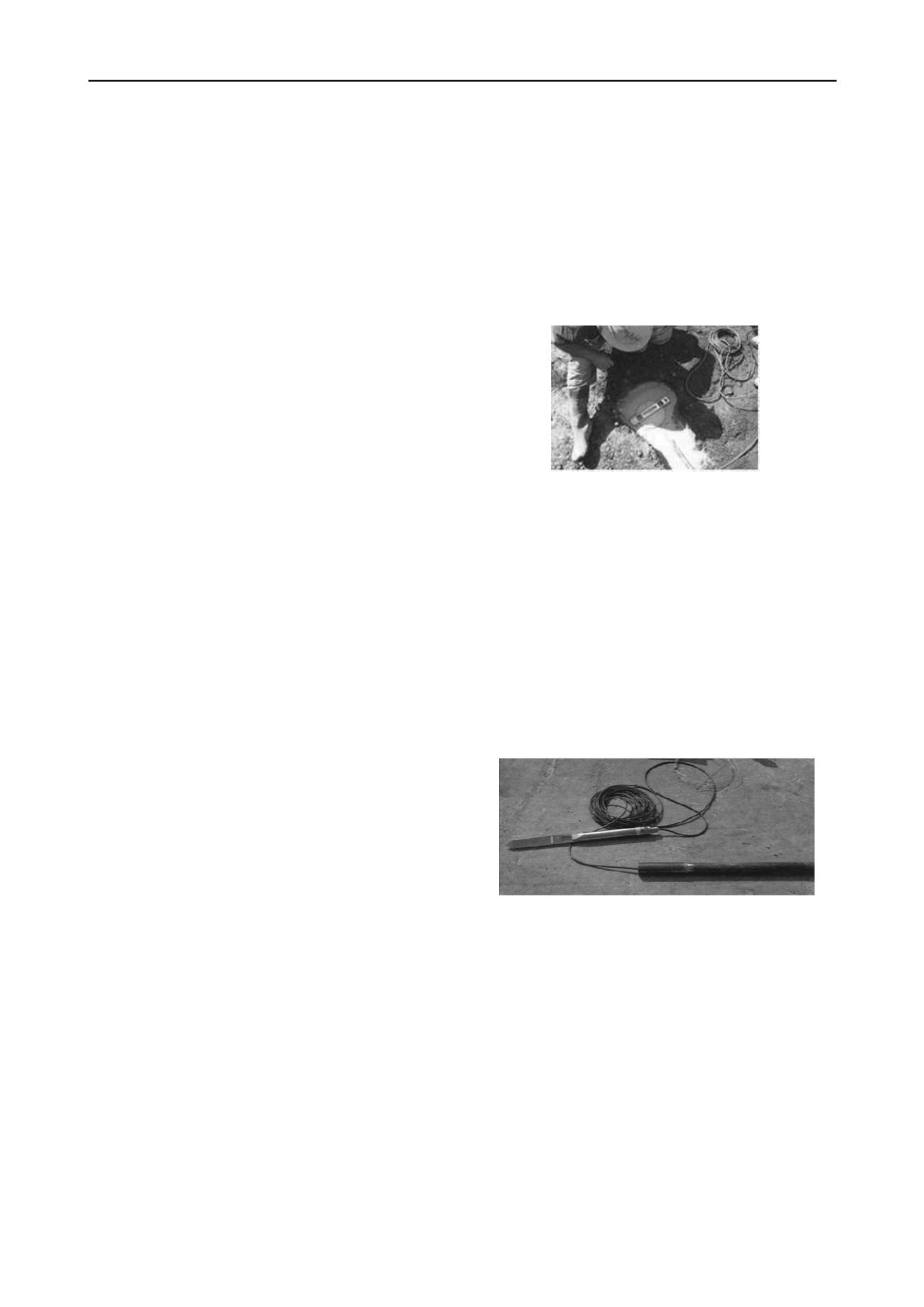
Penetrating pressure cells, known as push-in pressure cells,
Figure 3, were pushed in outside the walls in vertical position
and just at the contact with the clayey subsoil. This instrument
has a pressure cell to measure total horizontal stresses,
perpendicular to the wall, precisely at the exterior sides of the
structural cell. Three push-in-cells of SG type were installed;
each one has an integrated electric piezometer that records pore
water pressure at the foundation’s wall-soil contact. Two of
these sensors were placed in the South longitudinal wall, at one
and two thirds of the wall’s depth, and only one was placed in
the North wall at two thirds of its depth, Figure 4. Thus, with
the difference between total pressure and pore water pressure
measured at each push-in-cell, horizontal stresses were recorded
in terms of effective stresses.
Figure 3. Push-in pressure cell.
5.3
Resistive and vibrating wire piezometers
These were the first instruments to be installed, all embedded at
the soil-exterior wall contact, except one that was placed at the
inside wall-soil contact. The VW piezometers do not have a
rapid answer to pore pressure changes during seismic events, so
they will not be connected to the seismic data receiver.
Nonetheless, they do have the advantage of recording long term
pore pressure changes, with a consistent and very stable
manner. The SG piezometers will be connected to the digital
data recorder, because they have better dynamic response. This
has been verified in prior instrumentation projects, even
embedding the piezometers directly in clayey soil (Mendoza,
2004; Mendoza et al., 2000). The location of the six SG
piezometers and two VW piezometers is shown in the
foundation plan, Figure 4. Installation depth was derived from
the site stratigraphic conditions, seeking one and two thirds of
the wall-height, but embedding the sensors in clay.


