2806
Proceedings of the 18
th
International Conference on Soil Mechanics and Geotechnical Engineering, Paris 2013
5 CONCLUSIONS
0
0.1
0.2
0.3
0.4
0.5
0.6
0.7
0.8
0.9
1
0 0.1 0.2 0.3 0.4 0.5 0.6 0.7 0.8 0.9 1
Modulus Reduction, G/G
0
Mobilized Strength, q/q
max
= 1/FS
The upward and downward pile segments of an O-cell load test
can be conveniently represented by a versatile elastic continuum
solution. Results from seismic piezocone testing (SCPTu)
provide the necessary input data to evaluate axial side and base
resistances of the deep foundations, as well as the small-strain
stiffness (G
max
) needed for deformation analyses. Modulus
reduction is dependent upon mobilized capacity (P/P
ult
= 1/FS)
using a simple algorithm. A case study involving a two-level O-
cell arrangement for a large bored pile situated in the calcareous
Cooper marl formation of South Carolina was presented to
illustrate the application.
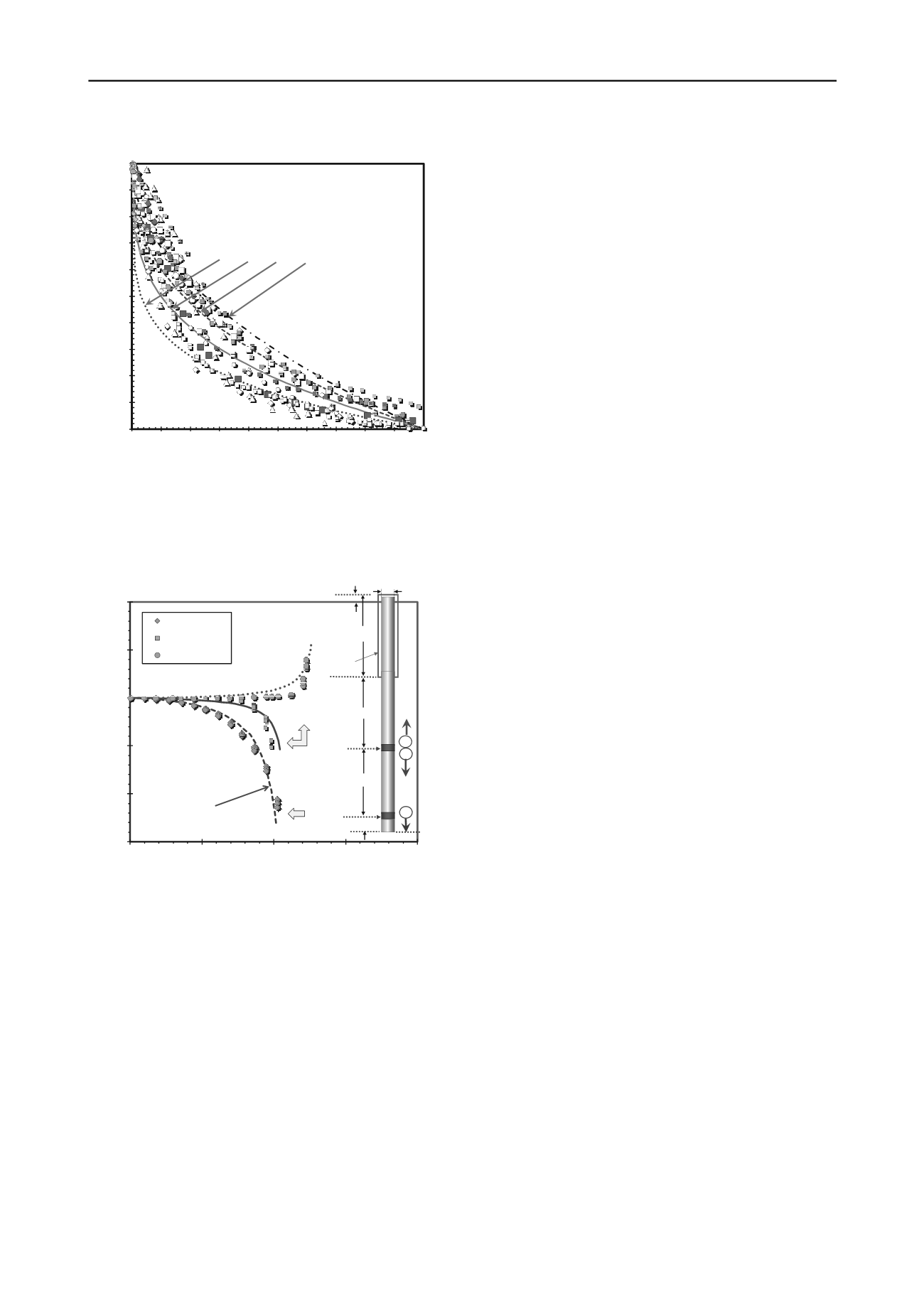
Algorithm: G/G
0
= 1 ‐ (q/q
max
)
g
Resonant Column,
Torsional Shear,
and Triaxial Data
g = 0.2 0.3 0.4 0.5 = exponent
ACKNOWLEDGMENTS
The writers thank Billy Camp of S&ME and the SCDOT for
providing access to the load test results.
REFERENCES
Camp, W.M. 2004. Drilled and driven foundation behavior in a
calcareous clay.
GeoSupport 2004
(GSP 124), ASCE, Reston,
Virginia: 1-18.
Figure 5. Modulus reduction algorithm for monotonic static loading
Camp, W.M., Mayne, P.W., and Brown, D.A. 2002. Drilled shaft axial
design values in a calcareous clay.
Deep Foundations 2002
, Vol. 2,
GSP No. 116, ASCE, Reston/Virginia: 1518-1532.
-150
-100
-50
0
50
100
Displacement, w (mm)
Eslami, A. and Fellenius B. H. 1997. Pile capacity by direct CPT and
CPTu methods applied to 102 case histories.
Canadian
Geotechnical J.
34 (6): 886-904.
0
10
20
30
40
O-Cell Load, Q (MN)
Meas. Stage 1
Meas. Stage 2
Meas. Stage 3
Shaft diameter
d = 2.6 m
L = 16.3 m
L = 2.5 m
L = 14.2 m
L = 14.0 m
1 m
1
2
3
Upper
O-Cell
Lower
O-Cell
Casing
10 m
20 m
30 m
40 m
0 m
Depth
Fahey, M. 1998. Deformation and in-situ stress measurement.
Geotechnical Site Characterization
, Vol. 1 (Proc. ISC-1, Atlanta),
Balkema, Rotterdam: 49-68.
Fellenius, B.H. 2001. The O-cell: an innovative engineering tool.
Geotechnical News Magazine
, Vol. 19 (2): 32-33.
Fleming, W G K, Weltman A J, Randolph M F and Elson W K. 1992.
Piling Engineering, 2nd Edition
, Blackie /Halsted Press - Wiley &
Sons, London: 122-128.
Mayne, P W. 2005. Integrated ground behavior. in-situ and lab tests.
Deformation Characteristics of Geomaterials
, Vol. 2 (IS-Lyon),
Taylor & Francis Group, London: 155-177.
48 m
Elastic Continuum
Solutionwith
SCPTu Data
Mayne, P.W. 2007a. In-Situ Test Calibrations for Evaluating Soil
Parameters,
Characterization & Engineering Properties of Natural
Soils
, Vol. 3, Taylor & Francis Group, London: 1602-1652.
Mayne, P W. 2007b.
Synthesis 368 on Cone Penetration Testing
,
National Cooperative Highway Research Program (NCHRP),
National Academy Press, Washington, DC: 117 p.
Mayne, P.W. and Woeller, D.J. 2008. O-cell response using elastic pile
and seismic piezocone tests.
Proc. Intl. Conf. on Foundations
(Dundee), British Geotechnical Association, IHS BRE Press, UK.
Figure 6. Measured and calculated O-cell response for test shaft MP-1
at Cooper River Bridge site
O'Neill, M W, Brown, D A, Townsend, F C, and Abar, N. 1997.
Innovative load testing of deep foundations.
Transportation
Research Record No. 1569
, Washington, D.C.: 17-25..
suggested for relatively insensitive clays, nonstructured soils,
and uncemented quartzitic sands (Mayne 2007a). For the
Cooper marl, the high calcium carbonate content would
implicate a rather structured geomaterial, therefore an
appropriate exponent "g" = 0.5 can be considered characteristic.
O'Neill, M W and Reese L C. 1999.
Drilled Shafts: Construction
Procedures and Design Methods
, Vols. I and II, Publication
FHWA-IF-99-025, Assoc. Drilled Shaft Contractors, Dallas: 758 p.
Osterberg J O. 1998. The Osterberg load test method for bored and
driven piles.
Proc. 7th Intl. Conf. Piling and Deep Foundations
(Vienna), Deep Foundations Institute, NJ: 1.28.1-1.28.11.
Using the aforementioned elastic continuum solution and
axial pile capacity determined from CPT results, together with
the initial shear moduli obtained from the V
s
profile, the
response of the three pile segments from the O-cell
arrangements can be represented, as shown in Figure 6 for test
shaft MP-1. A reasonable agreement is observed for all three
loading stages of both O-cell jacks, including an approximate
nonlinear load-displacement-capacity behavior.
Osterberg, J O. 2000. Side shear and end bearing in drilled shafts.
New
Technological and Design Developments in Deep Foundations
,
GSP No. 100 (Proc. GeoDenver), ASCE, Reston, Virginia: 72-79.
Randolph M F and Wroth C P. 1978. Analysis of deformation of
vertically loaded piles.
Journal of Geotechnical Engineering
Division (ASCE)
, Vol. 104 (GT12): 1465-1488.
Randolph M F and Wroth C P. 1979. A simple approach to pile design
and the evaluation of pile tests.
Behavior of Deep Foundations
, STP
670, ASTM, West Conshohocken, Pennsylvania: 484-499.
If desired, a more realistic compressible pile solution is also
available (Fleming et al. 1992), yet more complex as it involves
a hyperbolic tangent function. In that case, the developed curves
are quite similar to those shown herein.
Senneset, K., Sandven, R. and Janbu, N. 1989. Evaluation of soil
parameters from piezocone tests.
Transportation Research Record
1235
, National Academy Press, Washington, DC: 24-37.


