 
          2800
        
        
          Proceedings of the 18
        
        
          th
        
        
          International Conference on Soil Mechanics and Geotechnical Engineering, Paris 2013
        
        
          carried out a series of numerical analyses and proposed the
        
        
          following equation:
        
        
          ,
        
        
          ,


            PR UR UR ult


            PG u


            Q


            Q Q


            lt


          (1)


            PR


            Q


          ,
        
        
          and


            UR


            Q


            PG


            Q


          are the ultimate bearing capacities of the PR,
        
        
          the isolated raft and the isolated pile respectively;


            UR


          is a
        
        
          coefficient introduced to affect the raft bearing capacity when it
        
        
          is considered to be working in the pile-raft system.
        
        
          Numerical models were generated inducing settlements of 10%
        
        
          of the raft width, which are considered to be capable of
        
        
          mobilizing all the strength capacity of the system. The results
        
        
          were used to make out a numerical correlation to obtain the
        
        
          relation between


            UR


          and the geometry of the PR, which led to
        
        
          the following expression:
        
        
          1 3


            G


            UR


            A s


            A d


          (2)
        
        
          where


            G


            A


          is the area enclosed by the piles;


            A


          is the raft area;


            s


          and  are the pile spacing and diameter respectively.


            d


          3 APPLICATION OF THE LIMITE STATE METHOD
        
        
          (LEM) TO THE PILED RAFT FOUNDATION DESIGN
        
        
          The application of the Limit State Method (LEM) to the PR
        
        
          design to be described in this article is based on a design in
        
        
          which the piles behave as floating piles under ultimate or
        
        
          limiting capacity. It is one of the options that generate the
        
        
          greatest efficiency of the system, because it considers the piles
        
        
          working at their ultimate creep stages (Randolph 1994). This
        
        
          forces an analysis of the PR rather as a system than as
        
        
          independent elements, since the piles will be working at their
        
        
          ultimate stages and will consequently not satisfy any of the
        
        
          safety criteria established in pile design codes. Off course this
        
        
          obliges the contribution of the raft into design. Also, the safety
        
        
          coefficient of the mechanical characteristics of the soil can be
        
        
          applied to the mean values, as suggested by Quevedo (2002).
        
        
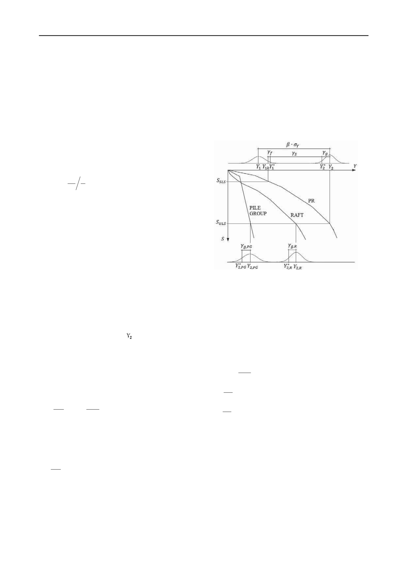
          Figure 1 shows how LEM concepts are introduced in the PR
        
        
          design. The resisting loads function  is determined as the sum
        
        
          of the raft average bearing capacity plus the respective one of
        
        
          the pile group, as shown by the following equation:
        
        
          2
        
        
          2,
        
        
          2,


            PG


            Y Y Y


            R


          (3)
        
        
          where
        
        
          2,


            R


            Y


          and
        
        
          2,


            PG


            Y


          are the raft and piles bearing capacity,
        
        
          respectively, calculated with average values of soil properties.
        
        
          The design load function of each element of the system can be
        
        
          obtained from the following equations:
        
        
          2,
        
        
          *
        
        
          2,
        
        
          ,


            R


            R


            g R


            Y


            Y


          ,
        
        
          2,
        
        
          *
        
        
          2,
        
        
          ,


            PG


            PG


            g PG


            Y


            Y


          (4)
        
        
          where
        
        
          *
        
        
          2,


            R


            Y


          and
        
        
          *
        
        
          2,


            PG


            Y


          are raft and the pile´s resistant loads,
        
        
          respectively. They can be calculated from the design values of
        
        
          the soil mechanical properties.
        
        
          By mean of the former definitions and Figure 1 it is possible to
        
        
          obtain the design equation for the ultimate limit state of a PR.
        
        
          *
        
        
          *


            PR


            S


            Q P


          (5)
        
        
          where is the overall vertical design load;
        
        
          *


            P


            S


          is a partial
        
        
          coefficient that considers the quality of the construction and the
        
        
          type of failure;
        
        
          *


            PR


            Q


          is the design load capacity of the PR
        
        
          obtained from equation 6.
        
        
          *
        
        
          *
        
        
          where
        
        
          and
        
        
          *


            UR


            Q


          *


            PG


            Q


          are the raft and the piles design bearing
        
        
          capacity respectively, calculated separately from the soil design
        
        
          values.
        
        
          The overall vertical design load can be obtained as a sum of the
        
        
          individual characteristic load weighted by a particular
        
        
          coefficient, as shown in the following equation:


          *


            ki


            fi


            P P


          (7)
        
        
          where is the characteristic loads and


            P


            ki


            fi


          are the weighting
        
        
          coefficients for the loads.
        
        
          Figure 1. Introduction of safety by the LEM in PR (Lorenzo 2010)
        
        
          In this article, the resistant load function and its design values
        
        
          are obtained in a manner that differs from the way they are
        
        
          normally obtained in structural analyses. As suggested by
        
        
          Quevedo (1987), Becker 1996), Gonzalez-Cueto (2000) and
        
        
          Lima (2006), the soil properties coefficients are applied directly
        
        
          to the mean values, while in structural design they are applied to
        
        
          the characteristics values.
        
        
          The design soil properties are calculated from values obtained
        
        
          from the statistical processing of laboratory tests results,
        
        
          weighting them by partial coefficients, as shown in equations 8,
        
        
          9 and 10.
        
        
          *
        
        
          1
        
        
          tan
        
        
          tan


            gtg


          (8)
        
        
          *


            gC


            C C


          (9)
        
        
          *


            g


          (10)
        
        
          where


          ,
        
        
          and


            C


          are the mean values of the soil internal
        
        
          friction angle, cohesion and specific weigh, respectively; and


            gtg


          ,


            gC


          ,


            g


          are the partial safety coefficients that affect
        
        
          each soil property.
        
        
          4 APLICATION OF SAFETY THEORY TO THE
        
        
          GEOTECHNICAL DESIGN OF PRF
        
        
          By means of probabilistic methods it is possible to calibrate the
        
        
          partial safety coefficients to be used in the LEM. This approach
        
        
          has not yet been introduced in the design codes. Consequently,
        
        
          the loads and resistance partial coefficients have not been
        
        
          establish as well. Nevertheless, the necessary expressions for
        
        
          the calibration of partial coefficients to use in the LEM can be
        
        
          developed by means of the general procedure described in
        
        
          Quevedo (1987). This author applied the procedure to the
        
        
          design of shallow foundations in cohesive soils and
        
        
          *


            PR


            UR UR


            PG


            Q


            Q Q


          (6)