2792
Proceedings of the 18
th
International Conference on Soil Mechanics and Geotechnical Engineering, Paris 2013
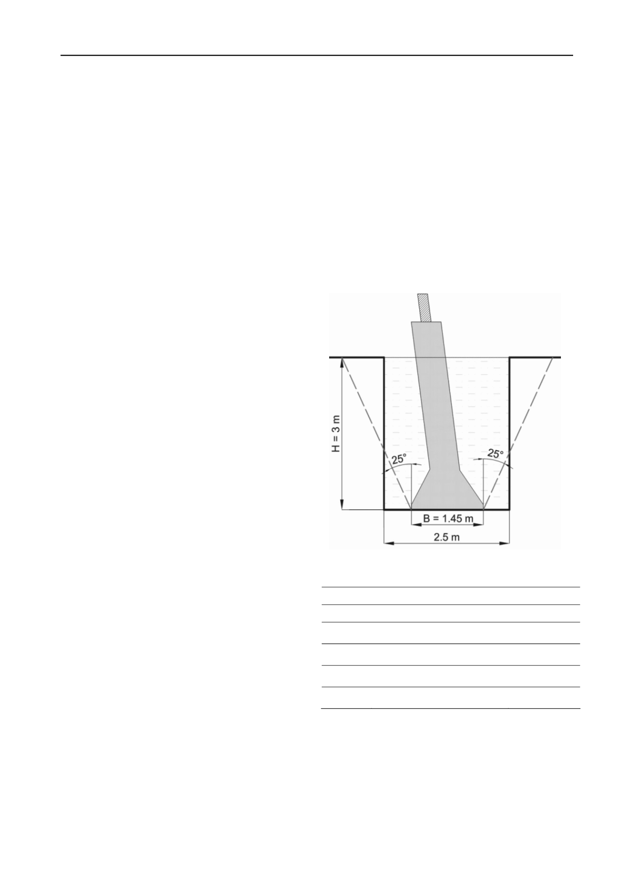
the pyramid is constructed of mass concrete. The footing is cast
inside a large excavation which is typically backfilled using the
excavated or imported material. In each case, the embedment
(H) to width (B) ratio is typically between 1 and 1.5.
1.2
Uplift resistance of footings
It is conventional to express the uplift capacity (Q
u
) of a footing
as:
Q = W
f
+ q
0
B
2
(1)
where
q
0
= N
uc
s
u
+γHN
us
(2)
The contributions from any base tension and backfill are
represented in Eq. 2 in the form of reverse bearing capacity
factors N
uc
and N
us
, respectively. The value of N
us
may be
quantified by a number of back analysed failure surfaces (e.g.
Murray and Geddes 1987) or through the use of design charts
derived from parametric numerical analysis (e.g. Merifield and
Sloan 2006).
Early physical testing at quasi static uplift rates investigated
the variation N
uc
with embedment ratio (H/B). There are
therefore many solutions available (e.g. Rao and Datta 2001).
However more recent centrifuge studies have shown that N
uc
is
also dependent on uplift rate (v
f
) (Lehane et al. 2008). Under
rapid loading (v
f
= 30mm/s) it was found that a single footing
founded on kaolin clay generated more than twice the capacity
in comparison to a slow uplift rate (v
f
= 0.3mm/s). The
difference in uplift capacities between v
f
= 0.1mm/s and v
f
=
30mm/s was proportional to the reduction of pore water
pressure below the footing base (Lehane et al. 2008). It was
proposed that the slow uplift rate allowed suction relief to occur
due to the gradual base/soil separation during uplift. This is
sufficient to relieve suctions and at approximately w/B≥6%
residual capacity was equivalent to a full breakaway condition.
Backfill
London clay
At very fast uplift rates (v
f
> 30mm/s) base separation does
not occur due to the full development of suctions that eventually
cause a reverse bearing failure to occur in the clay. This type of
failure results in a clay wedge remaining adhered to the footing
base post-pullout and capacity is determined by the undrained
shear strength of the clay (fully bonded).
2 FIELD TESTS
The aim of the field tests was to reduce the uncertainty
surrounding the in situ performance of transmission tower
footings. Reduced scale physical model tests conducted in a
geotechnical centrifuge demonstrated that during continuous
pullout out at increasing velocities that uplift capacity may be
significantly enhanced due to the development of suctions
occurring across the footing base. It was shown that uplift
capacity had a log linear relationship with the uplift velocity
(Lehane et al. 2008). The source of this contribution was the
formation of negative pore water pressures on the footing base.
However it is only at field scale that these effects can examined
and quantified in the context of realistic in situ soil conditions
and construction variabilities associated with full scale
footings..
To examine these issues a series of full scale tests were
commissioned at the Building Research Establishment's London
Clay test site at Chattenden, Kent (OS ref: TQ 75521 73987).
The field tests aimed to bridge understanding of the load-
displacement, load-rate and suction behaviour of soils from
small scale and numerical modelling to field scale. By using
different construction backfill materials to replicate as-built
construction practices, uplift rate and base interfaces across five
L4M tower type footings (Footings 1-5) that different uplift
mechanisms at full scale could be revealed.
2.1
Site layout
Five L4M footings were constructed at the Chattenden site in
August 2010. The footing geometry used is shown in Figure 1.
The footings were designed and constructed to TS 3.4.15 Issue
2 (National Grid 2004). The design uplift resistance (Q
des
) of the
footings using TS 3.4.15 was 420kN based on a 25
o
frustum
angle as s
u
>50 kN/m
3
on the founding plane (Butcher et al.
2009).
Each footing was installed with different base contact
conditions and backfill material (see Figure 1.). These variables
allowed the contribution of each resistance mechanism to be
isolated. Footings 1 and 2 were backfilled with tumbled and
compacted London clay – representing field/early construction
practices. Footings 3-4 used DoT Type 2 backfill - a coarse
granular material from recycled aggregate (Depart of Transport
2009). All footings were directly cast on the underlying clay
apart from Footing 3, which had a Type 2 free drainage layer.
Figure 1. L4M footing with a 25
o
frustum
Table 1. Footing specifications
Footing
Backfill
Base
1
Loose London clay
London clay
2
Dense London clay
London clay
3
Type 2
Type 2
4
Type 2
London clay
5
Type 2
London clay
2.2
Ground conditions
The Chattenden site has been used extensively for
foundation testing due to the presence of the deep and uniform
London clay strata (e.g. Butcher et al. 2009). The depth of the
London clay strata is ~30m and it was evident that during the
construction of the footings that the top 3m was heavily
weathered and fissured. The foundation tests were conducted
over a two week period in July 2012. The extremely wet
summer of 2012, particularly in the weeks prior to the field tests
resulted in the top layer of weathered clay became soft
(~s
u
=10kPa). It was also evident that the excavations backfilled


